Since I’ve built a lot of multirotors, most with the sole purpose of being aerial photography platforms, I thought it was about time to make a toy copter instead. I got some inspiration from a pal who sent me a lot of youtube videos of people having fun with theese small creations, and well – I fell for it and started constructing my own.
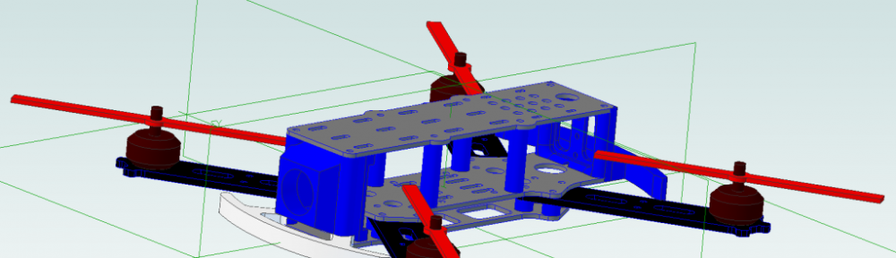
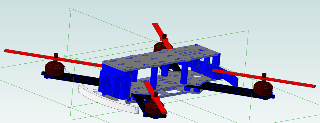
The main idea was to make a small, lightweight quadcopter using only my CNC-mill, the 3D printer and standard off-the-shelf parts. I took the measurements of some chineese electronics found on banggood.com and two nights later the CAD-drawing was complete.
What you will need to build this quad is (Bill of Materials), observe that the links are to the items I’ve used for my project, you may use other stuff, theese are confirmed to work with my specific setup:
- 4pcs 2300-ish Kv motors, 250 size (Link)
- 4pcs 12A ESC (Link)
- Flip32 or Naze32 or similar Controller board (Link)
- 2pcs CW + 2pcs CCW propellers 5″ (Link)
- 1500mAh 3cell LiPo battery (Link)
- 16mm long 3mm screws with nuts (35pcs)
- Radio and reciever, I used an S.Bus Futaba system
And for the FPV part
The first thing to do is to download all the models from here:
The DYI 250 size quadcopter drawings.
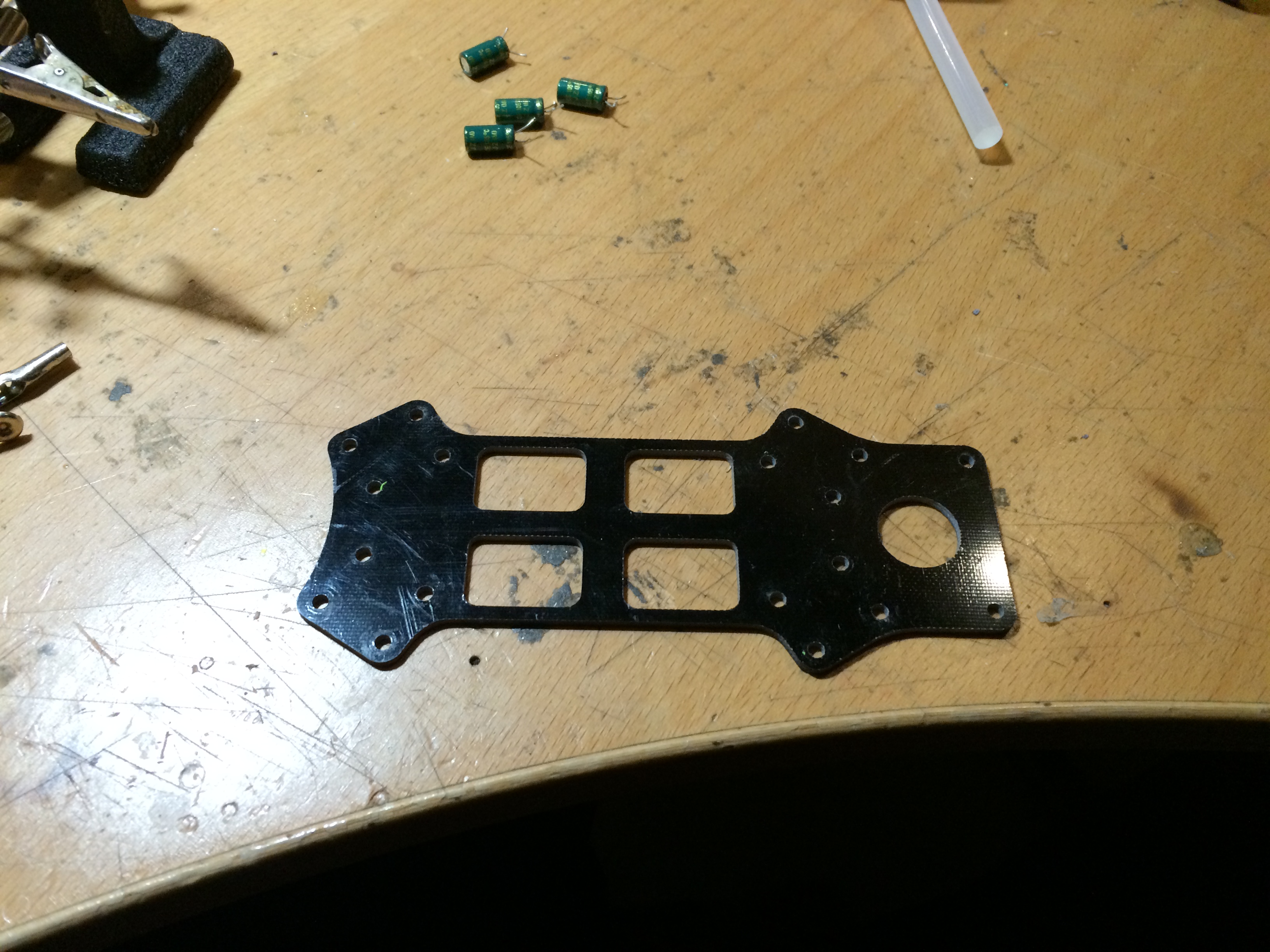
I used G10 material for the milled parts, and PLA plastics for printing the .STL files, but you can choose the materials you prefer. You need to make the following:
- Mill 4pcs arm.dxf from 3mm material
- Mill 1pc base_plate.dxf from 1.5mm or 2mm material
- Mill 1pc bottom_plate.dxf from 1.5mm or 2mm material
- Mill 1pc top_plate.dxf from 1.5mm or 2mm material
- Print 16pcs 5mm_plastic_distance.stl
- Print 4pcs 29mm_top_distance.stl
- Print 1pc back_plate.stl
- Print 1pc cam_house.stl
- Print 1pc led_bumper_front.stl
- Print 1pc led_holder.stl
Now you have all the parts needed to build the quad, start with the bottom plate.
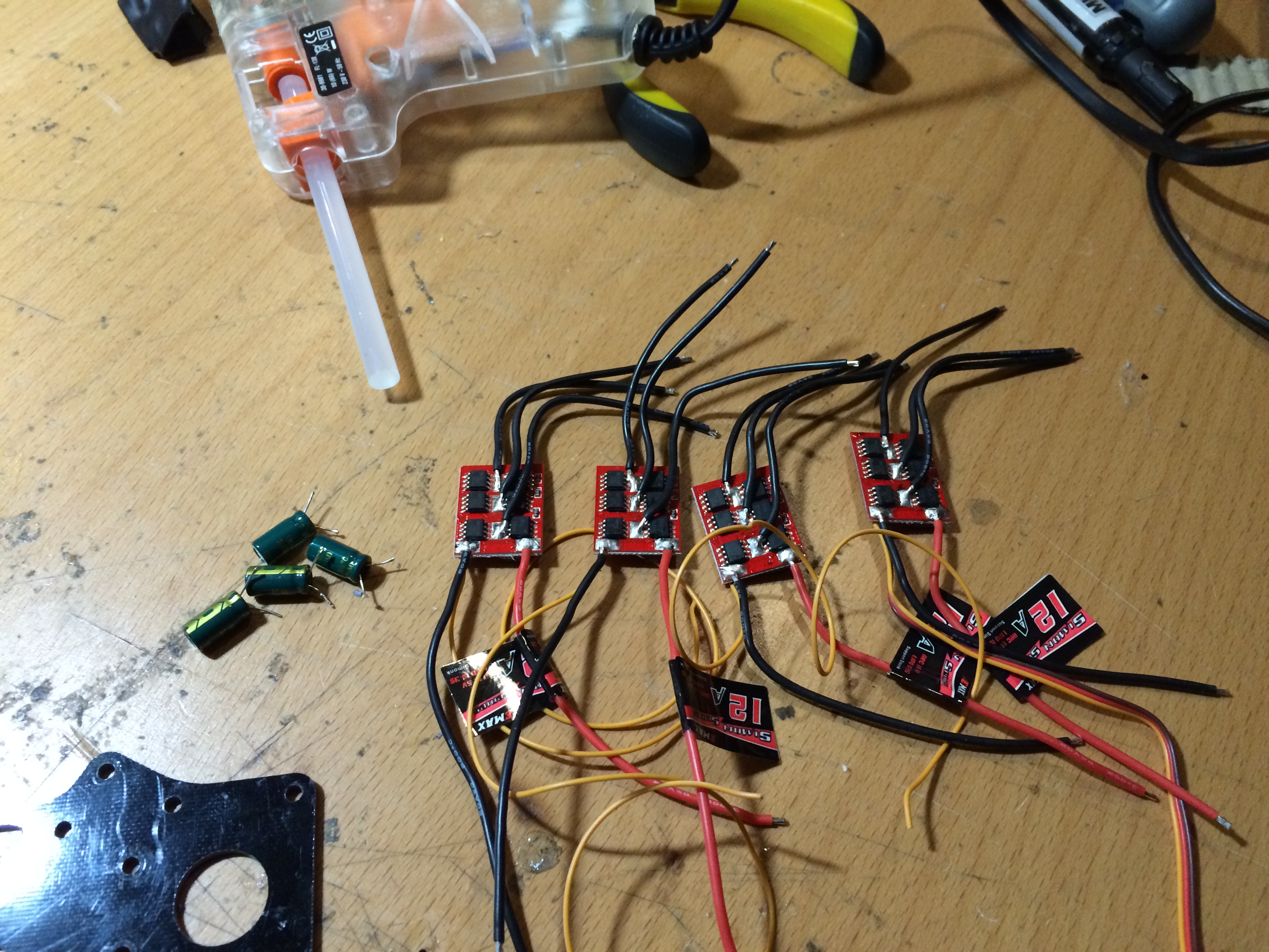
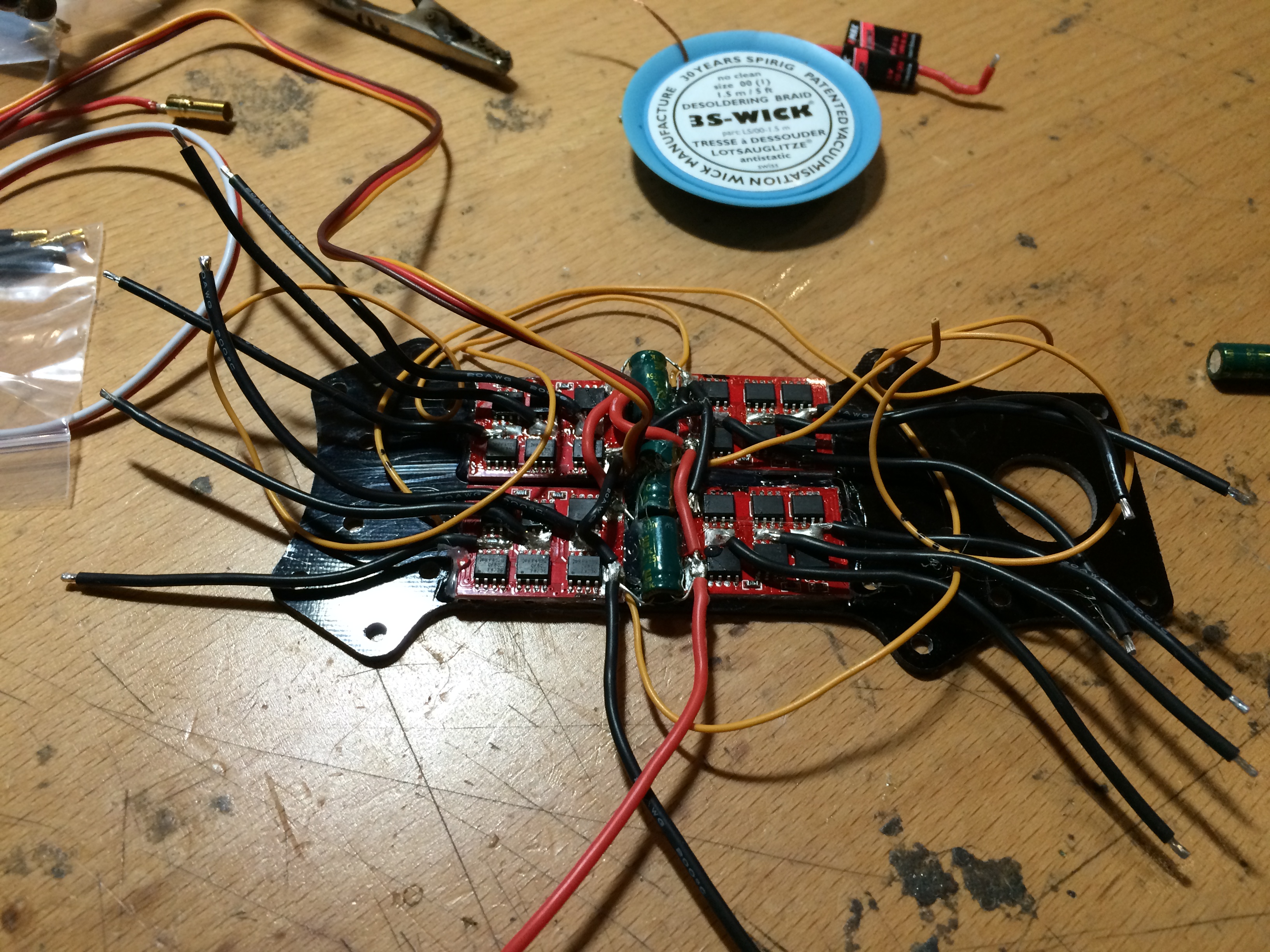
To make the ESC:s fit nicely I removed the shrink-wrap and de-soldered the capacitors from the power feed to the ESC:s. Make sure the ESC:s work before doing this since you WILL void the warranty.
 The next step is to hot-glue the ESC:s to the bottom plate of the quad:
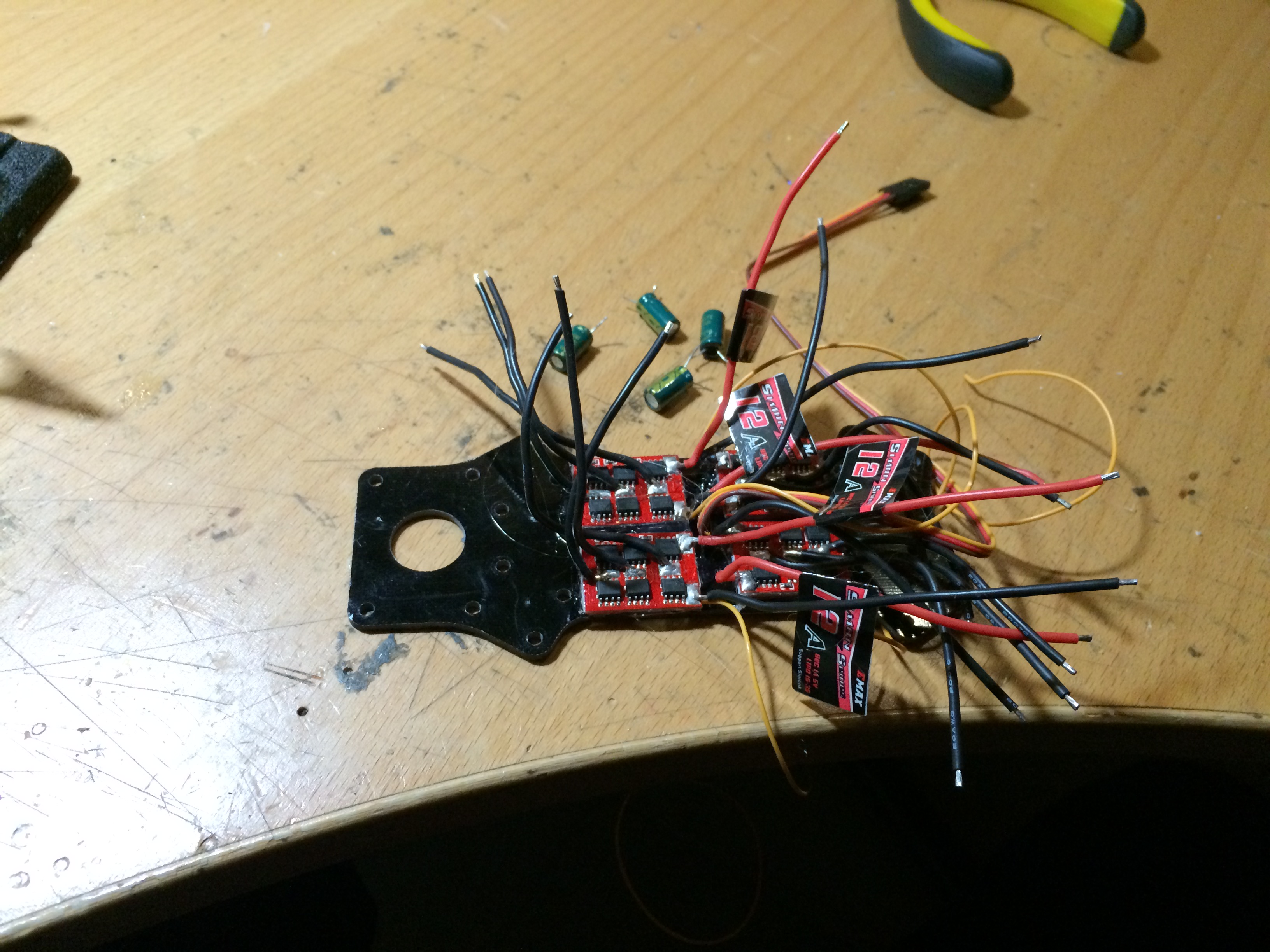
After this I removed all but one of the 5v feed and ground wires from the BEC side of the esc, just keeping the yellow signal-wire. I re-soldered all the power feed wires to only let two wires leave the bottom plate with the ESC installation, and made sure all the ESC:s was fed properly from theese two wires. Finally I re-soldered three of the four capacitors, that SHOULD be enough to keep the voltage stable.
Now the bottom-plate ESC installation is complete, and we keep building upwards. Mount the four 29mm distances to the middle holes on the base-plate, and mount the arms to the base-plate with 16mm screws : base-plate, arm, 5mm distance, bottom-plate.
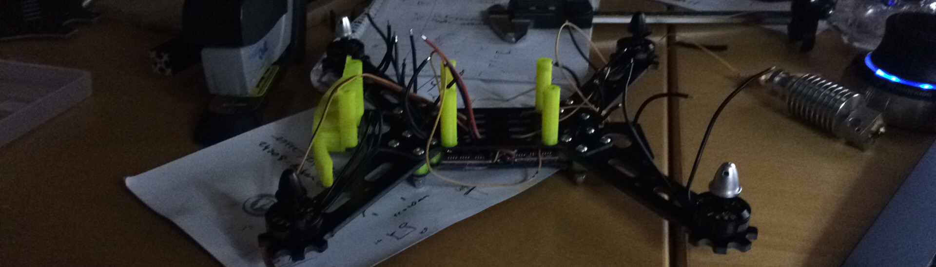 I used nyloc nuts to make sure the arms wouldn’t come undone from the vibrations.
I now installed the motors on the arms, this can be left until later to keep the wiring tidier while installing the controller board, but it really makes no difference. Here you can see the routing of the motor wires:
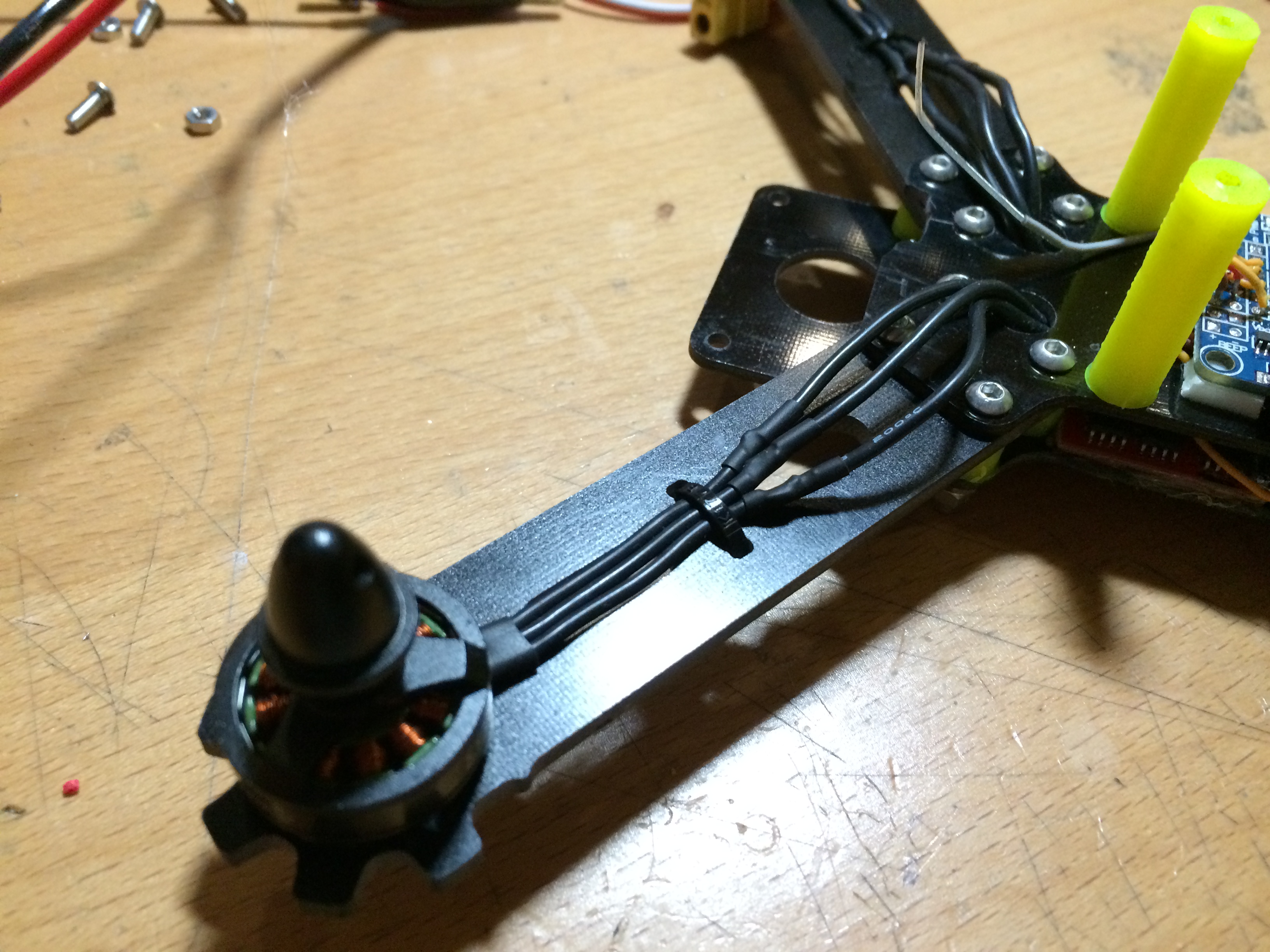
Make sure not to route the wires through the holes in the arms as this will make you have to de-solder and re-solder the wires if/when you snap an arm when crashing. 😉
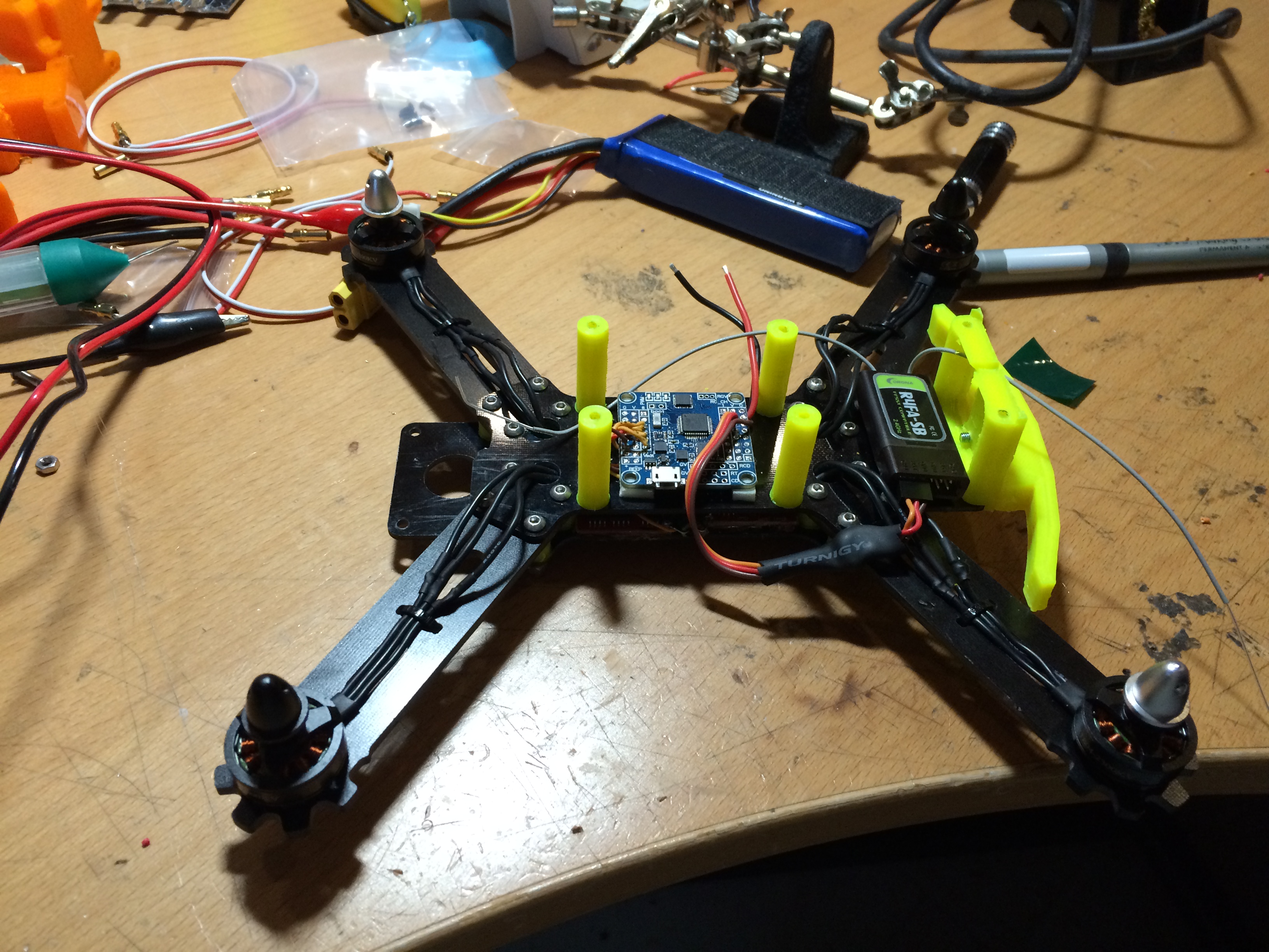
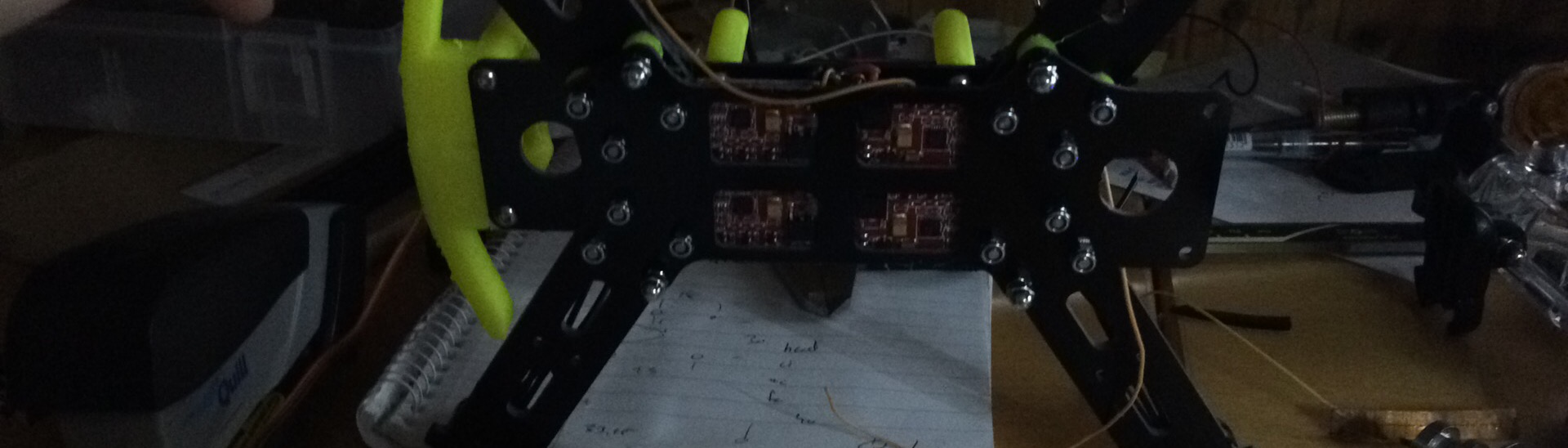
Now it’s time to install the controller board. Since I cut all the signal wires from the ESC:s I solder them directly to the motor outputs of the controller board. Make sure you solder them in the right positions, I had to re-do this a couple of times to get it right due to sloppyness.. 😉
Since I’ve got a Futaba radio and want to keep the quad tidy I want to use the S.bus protocol to connect the reciever to the controller board. To do this, the Flip32 controller needs for the signal to be inverted before connecting it to RX input signal pin #4 on the controller. This I did using a 74HC14D Hex inverting Schmitt trigger SOP-14 that I bought for 18 cents on EBay. I soldered the inverter onto the signal cable directly, the black blob you see in the picture above next to the reciever. This turned out to work perfectly!
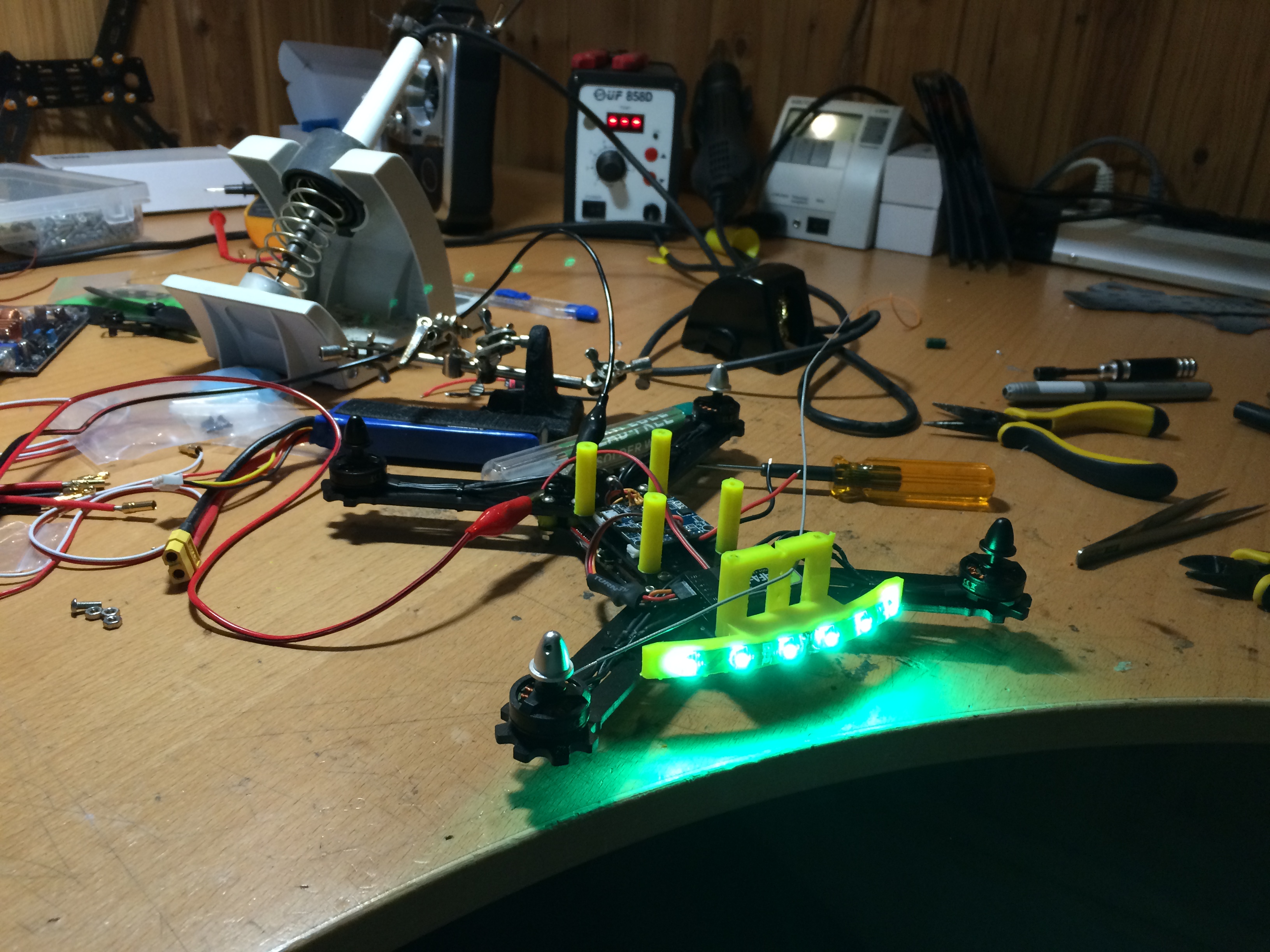
Next mount the back-plate at the far back of the quad, and mount the led-holder to it. I stuck a green LED-stripe to the holder and routed the wire from the center of the stripe, underneath the quad and to the center of it, looks quite good:
Now, mount your camera to the camera holder, and mount your video tx to the back of the top-plate. I routed the tx antenna through the hole in the center of the plate to protect the tx connector from force on impact.
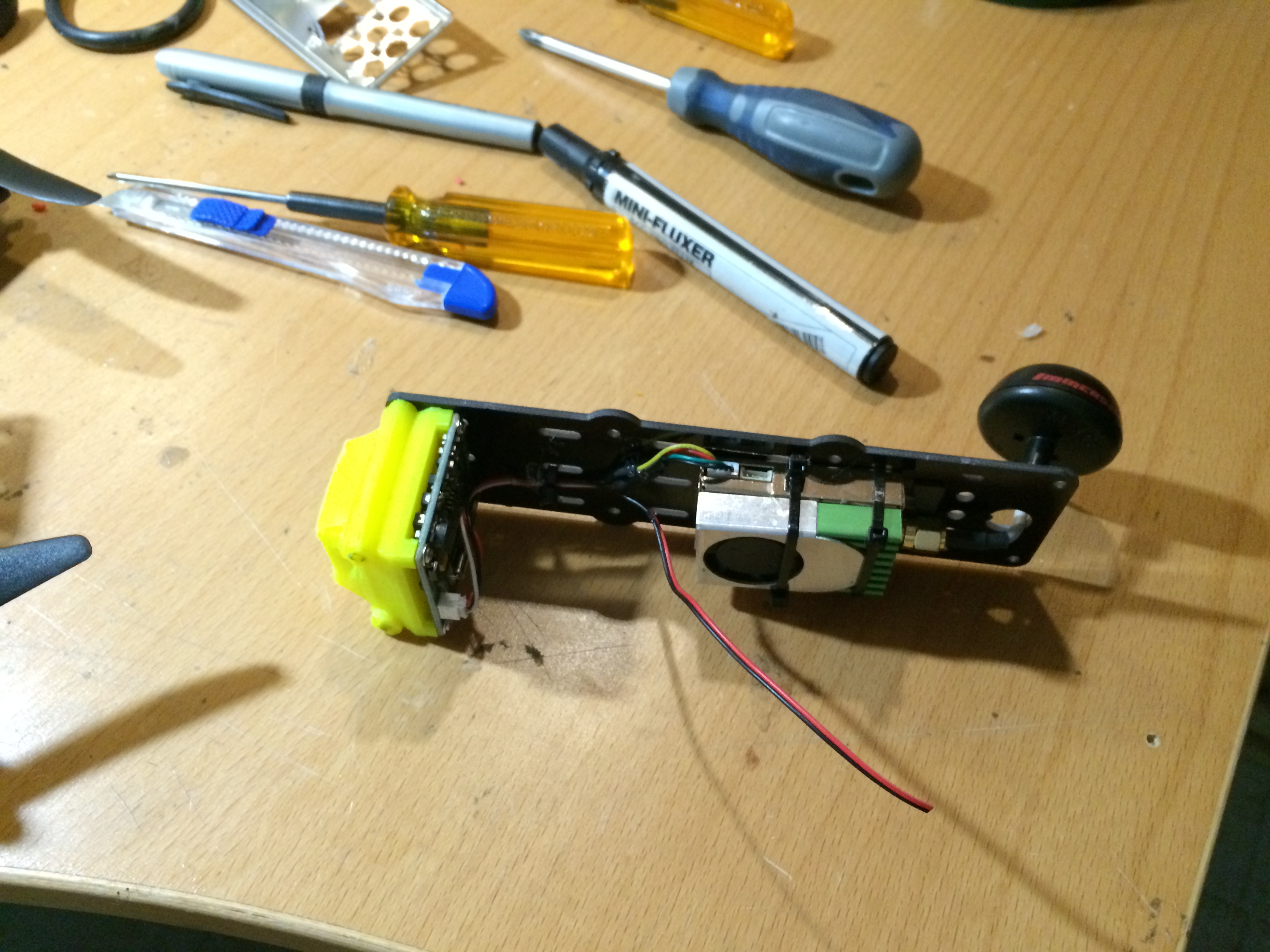
As you can see this is not the video transmitter from the BOM, but a huge tx that I used only for testing purposes. You can however get and idea of how the camera and video-tx is mountet to the top-plate in the picture.
It’s now time to solder the power connector to the power feed cables. Since my controller has a voltage-monitoring function I soldered a bunch of wires in the same connector:
- Power supply to the ESC:s
- Voltage mointoring to the controller board
- Power to the front- and rear LED-stripes
- Small power connector to connect to the video-tx and camera
Now mount the top-plate on top of the chassis you’ve built, and under the front bolts attach the led-bumper-front, installing a LED-stripe to it in the same way as in the back.
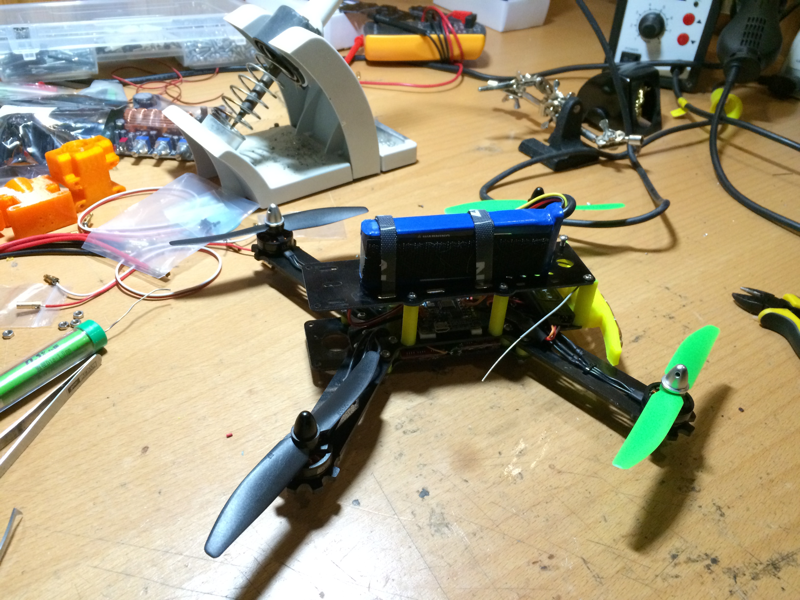
Here the camera is not installed, but it’s good for a test flight. Just do the proper setup for your controller board, attach a battery pack and try it out. My smaller batteries haven’t arrived yet so I’m using a 2200mAh 3cell LiPo battery and the quad flies nicely with this setup.
Any requests or questions, feel free to comment this post.
Small film of one of the first stable test flights:
http://youtu.be/fntY-7YglDU
Just had it out for a spin, and it is ridiculously stable in the air. No fiddeling with the PID:s, just flashed CleanFlight fw into my Flip32 controller, turned on Angle-mode and took of. Super steady and SUPER FAST!
Yeehaa!