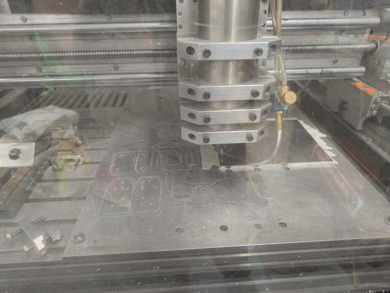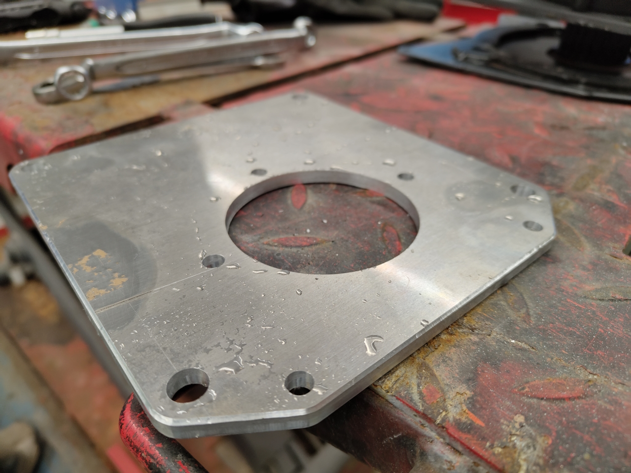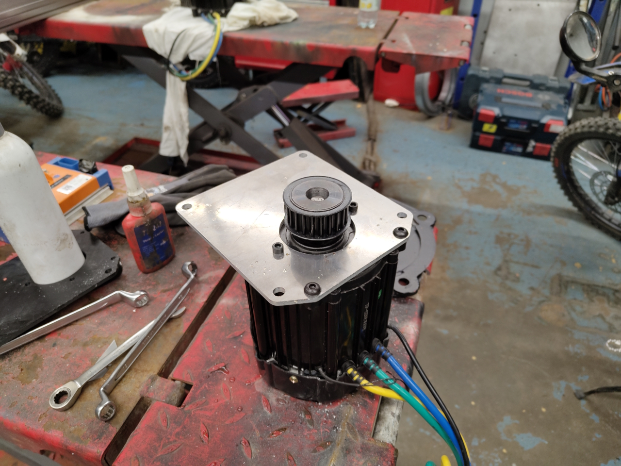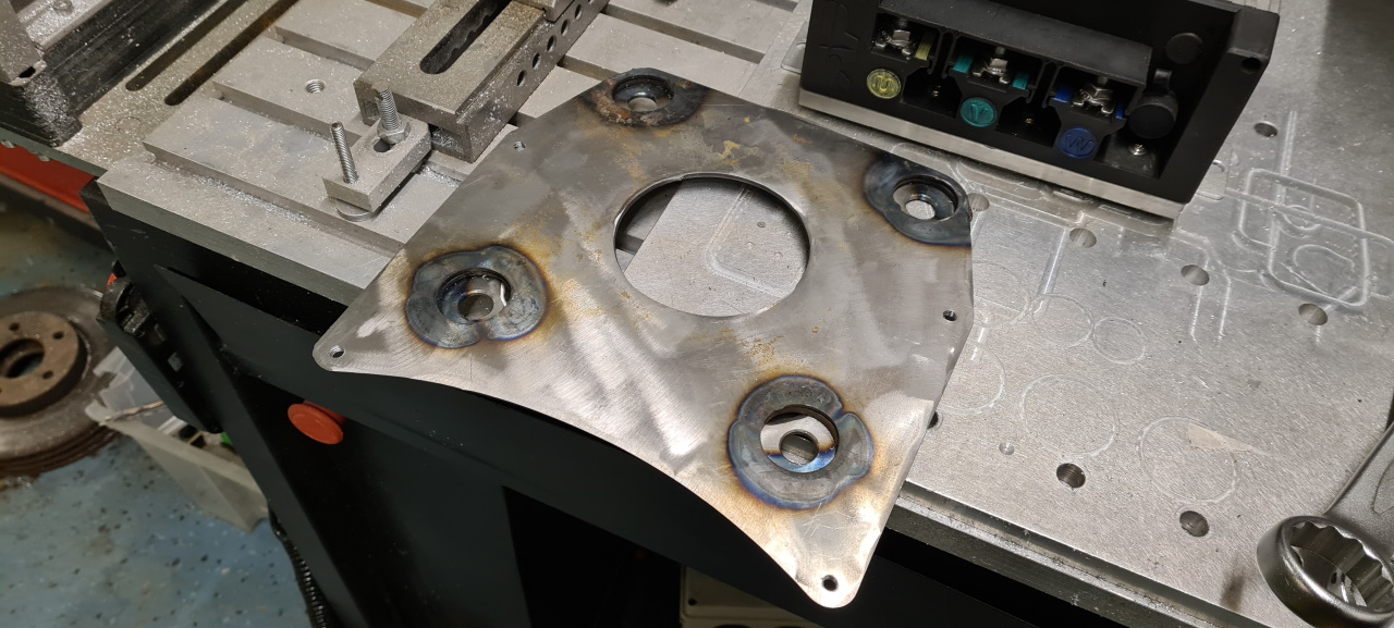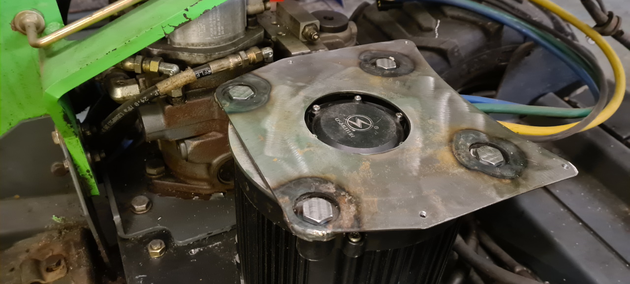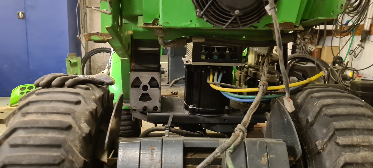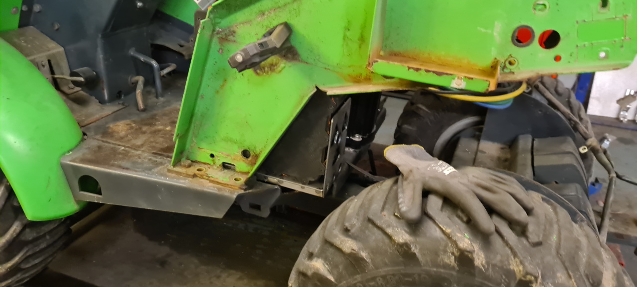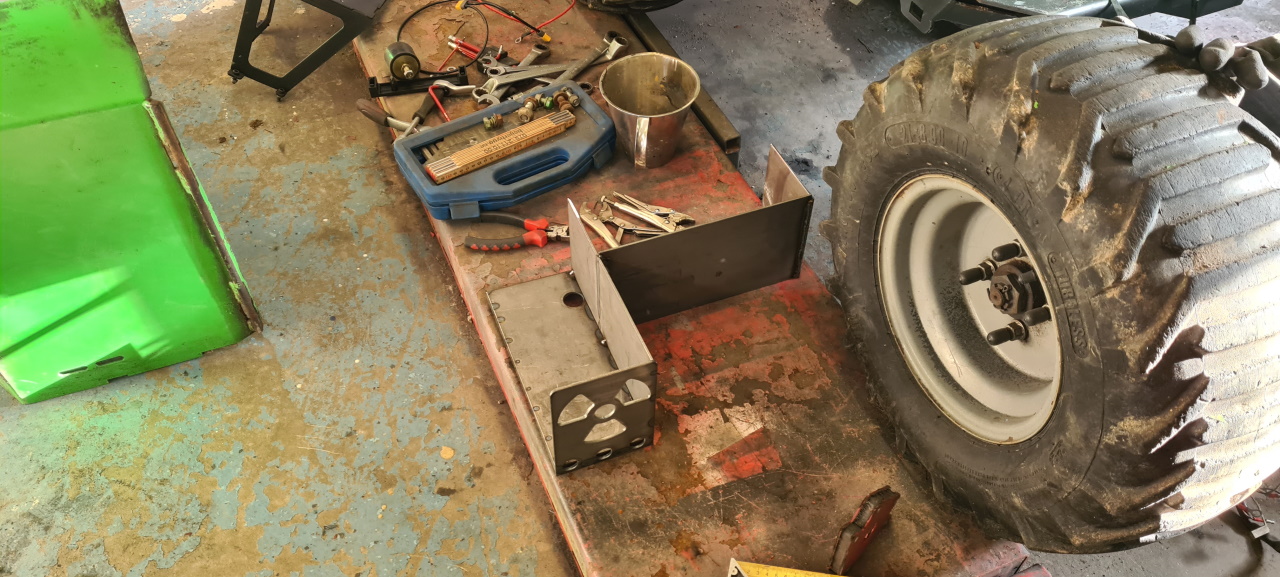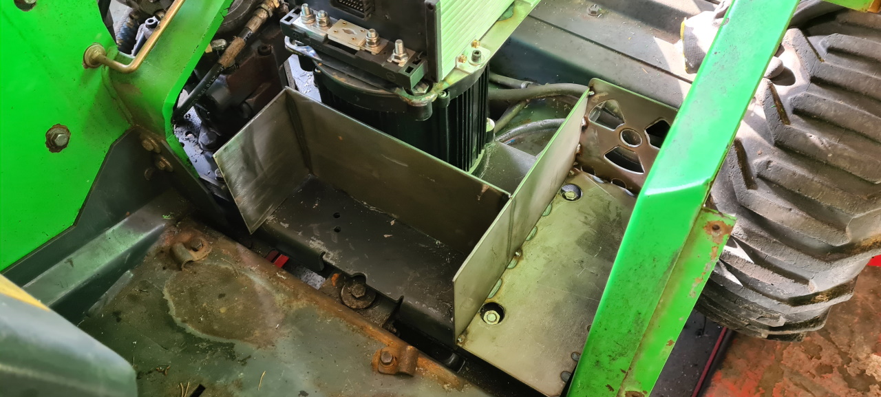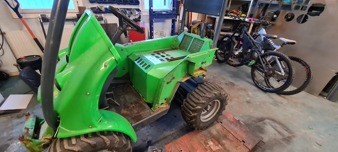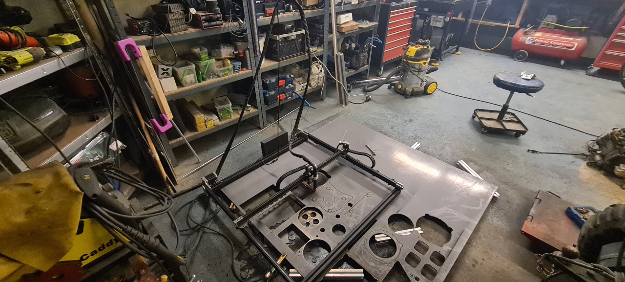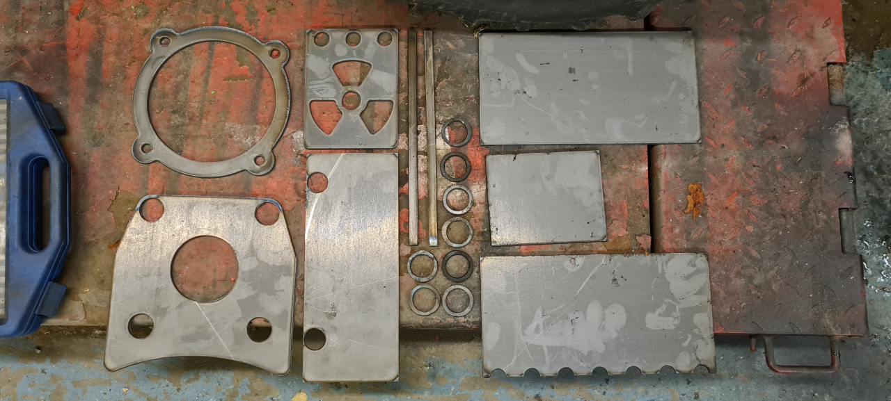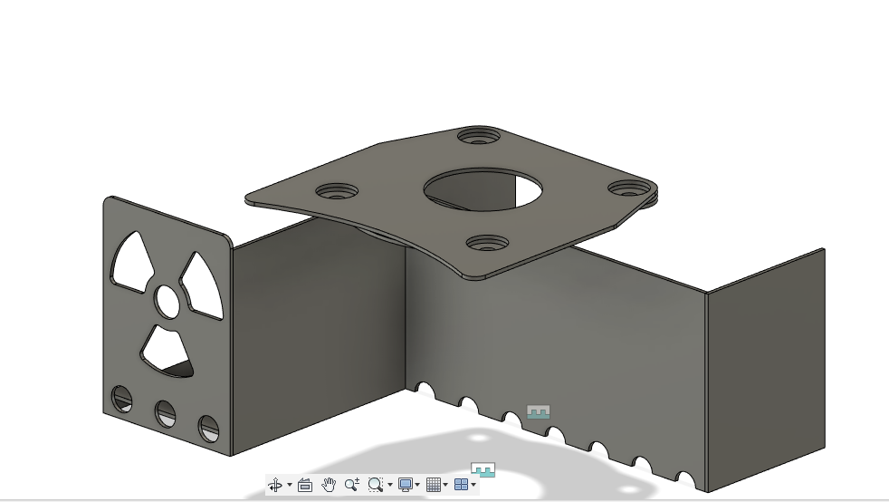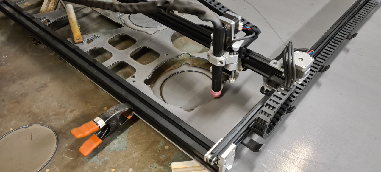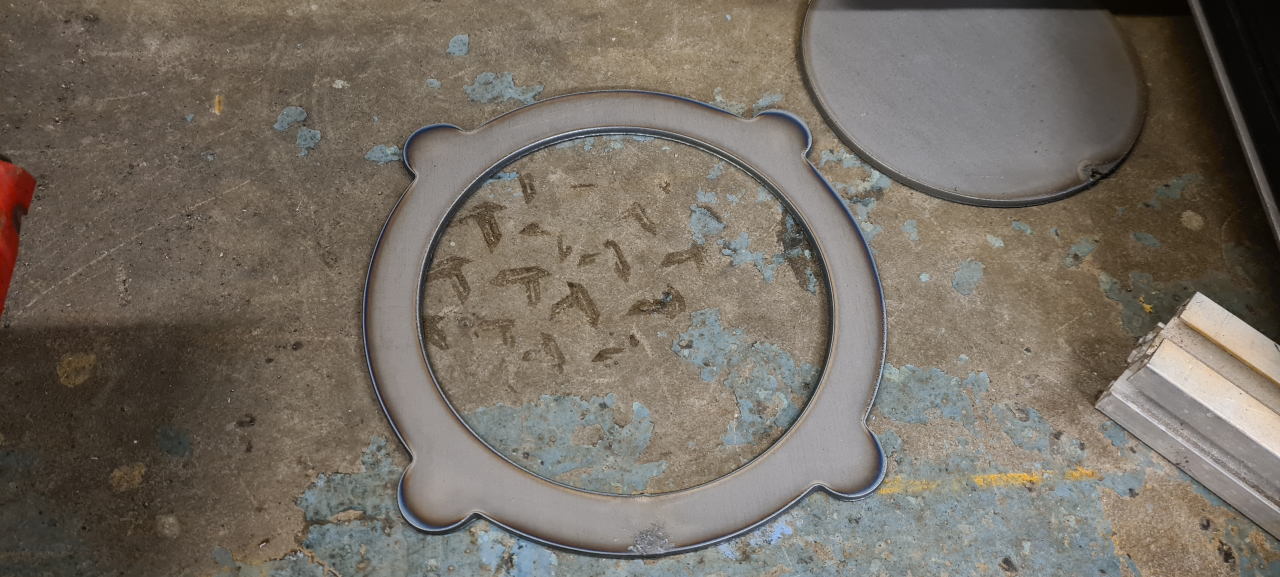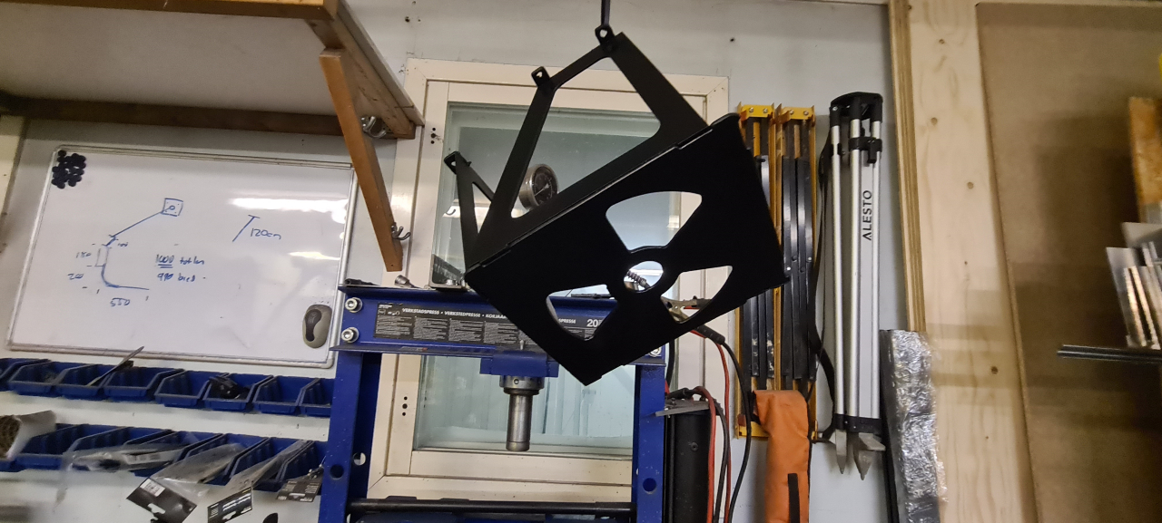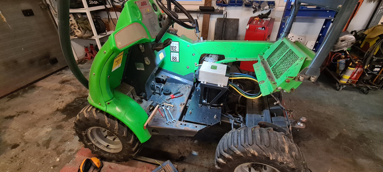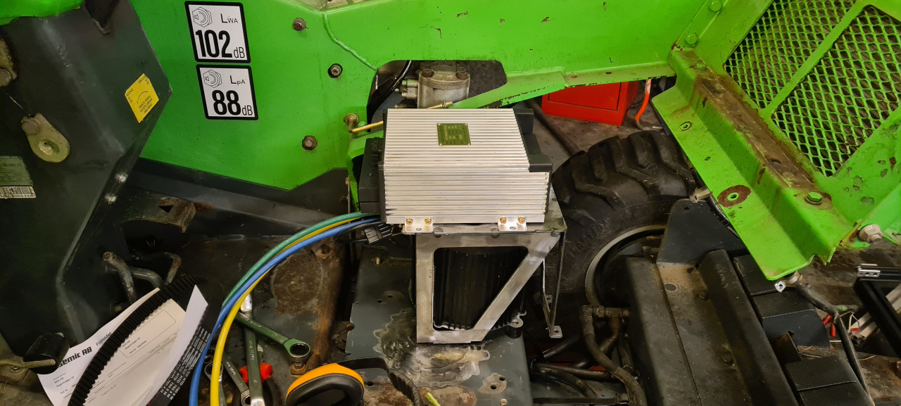
So, after having made the physical conversion with the mounting plate all that was left was the electrical..
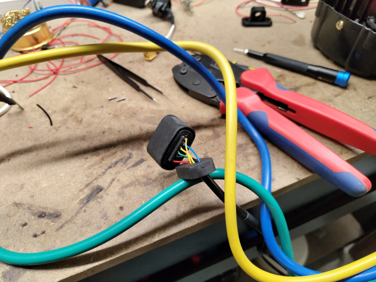
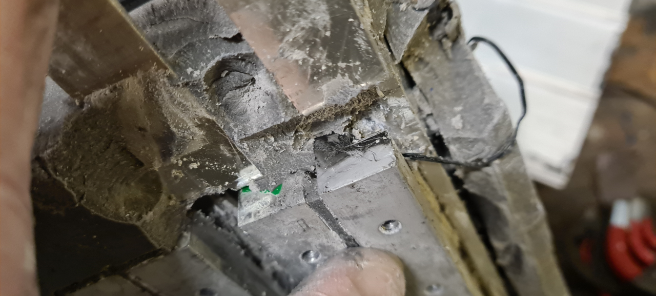
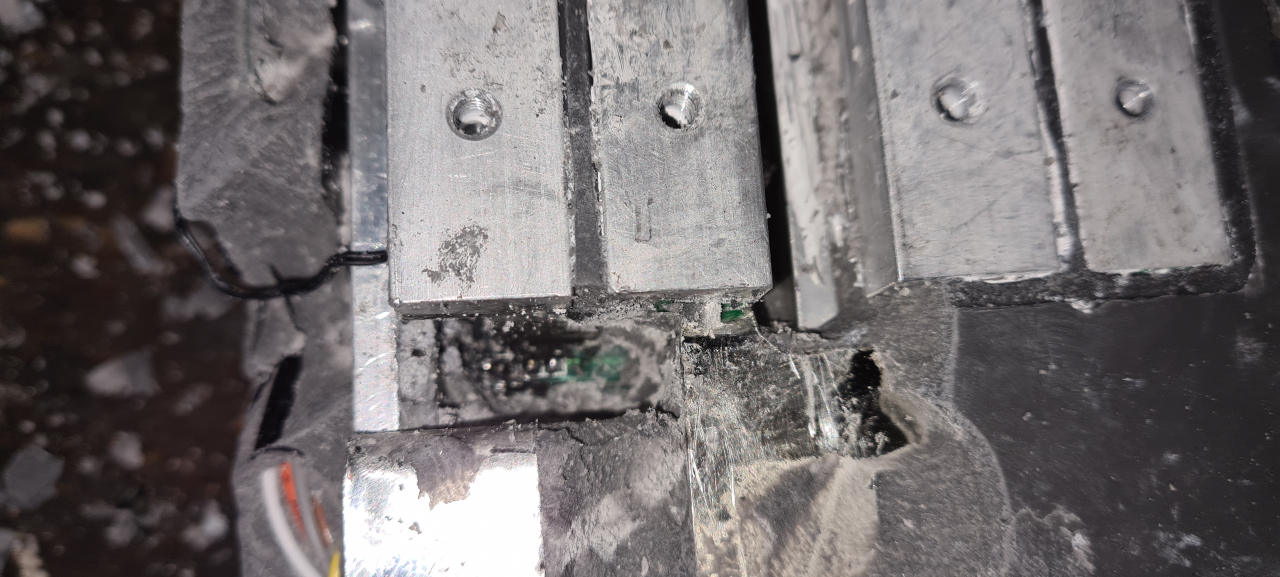
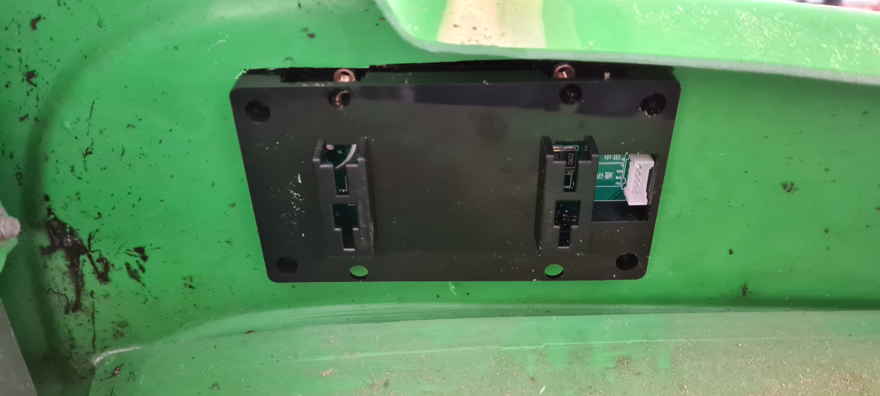
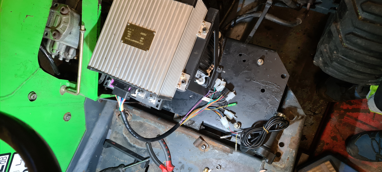
To fit the ASI BAC-series of controllers the hall sensors and thermistor needs a 6-pin molex plug. Those are super hard to come by. Sure, I could buy a complete adapter from the US, but that’d take far too long.. So I 3d-printed a molex plug, the crimp connectors I already had.
A resin printed plug with TPU seals will have to do. It’s pretty sealed and I could fill it with hot glue if needed later. Here I made a mistake though. I used the schematics for the BAC855 controller to deduce the pin numbers for the different hall sensors, and I got it wrong..
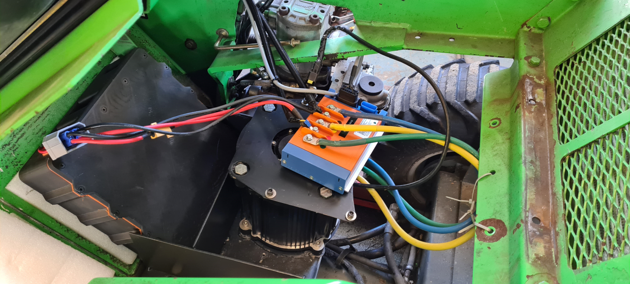
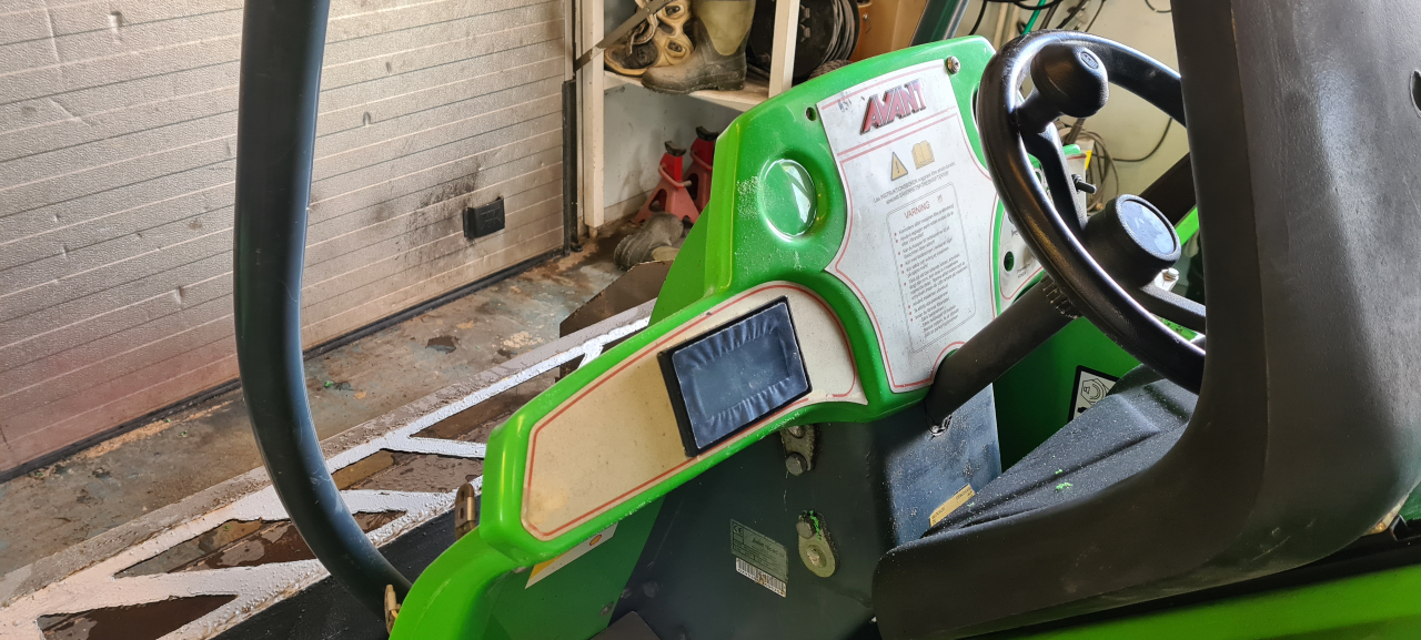
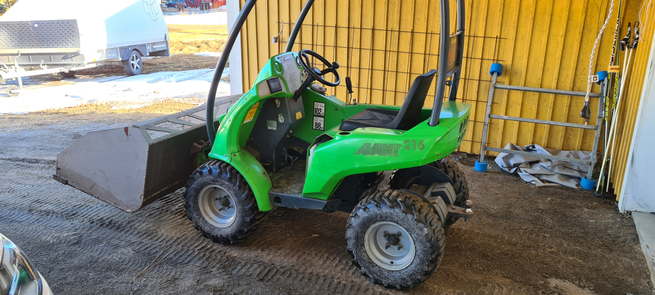
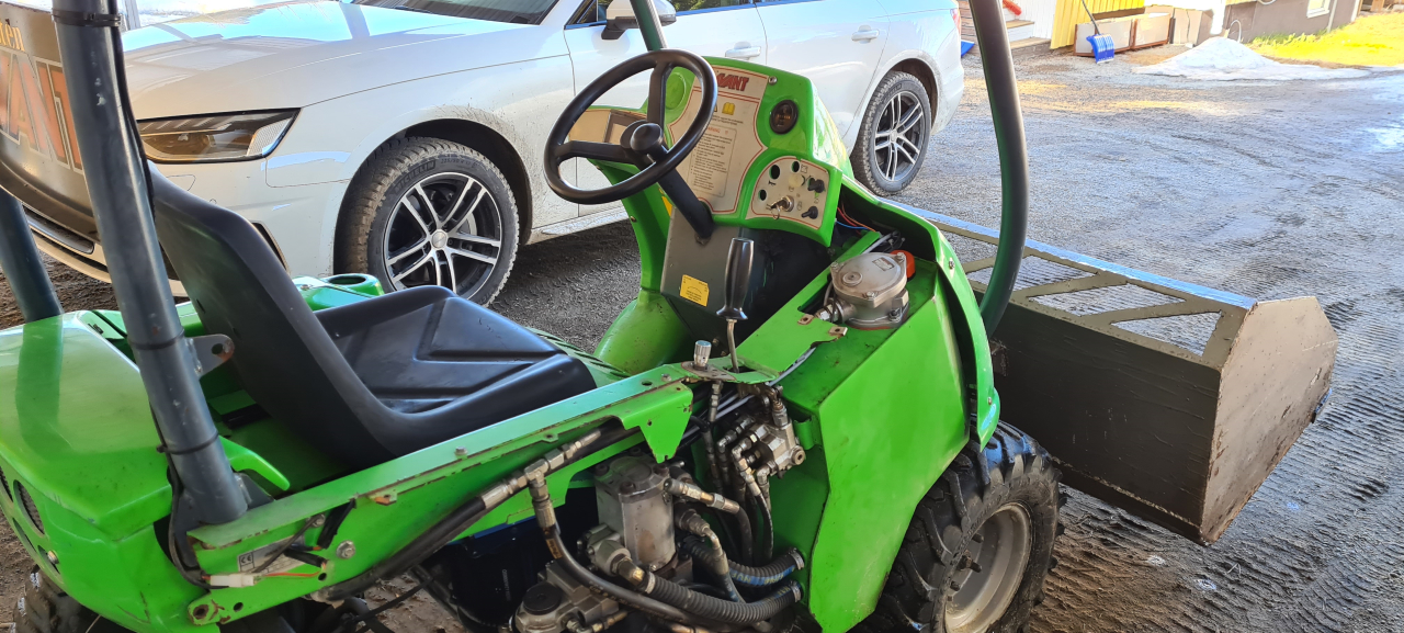
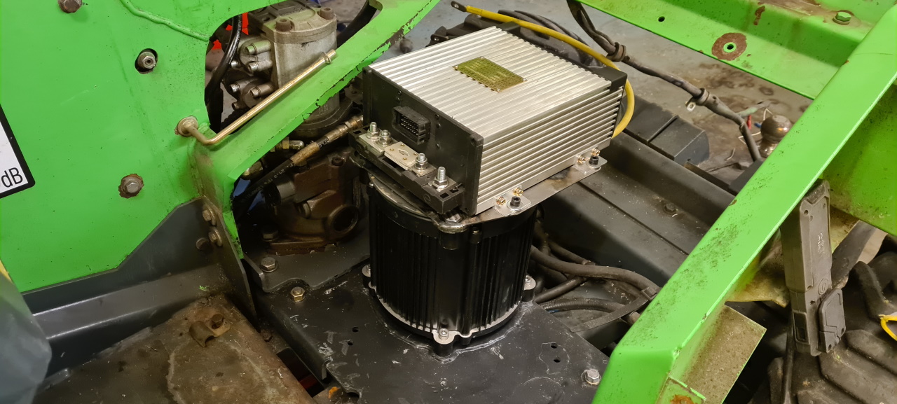
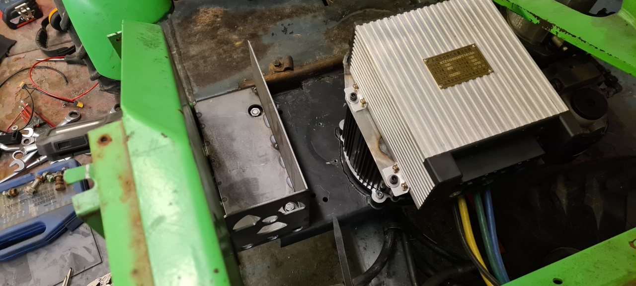
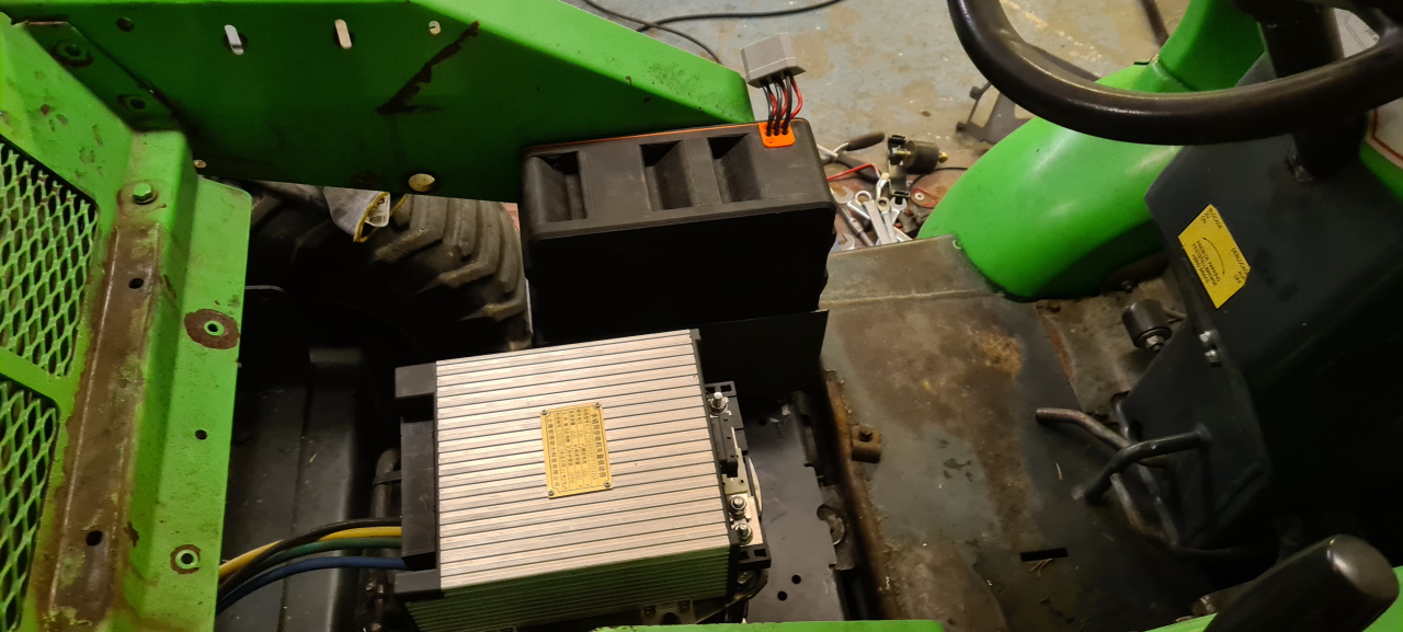
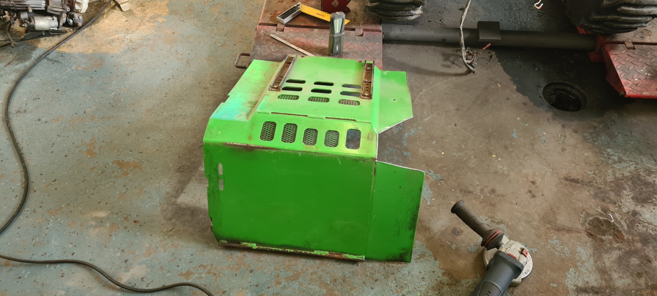
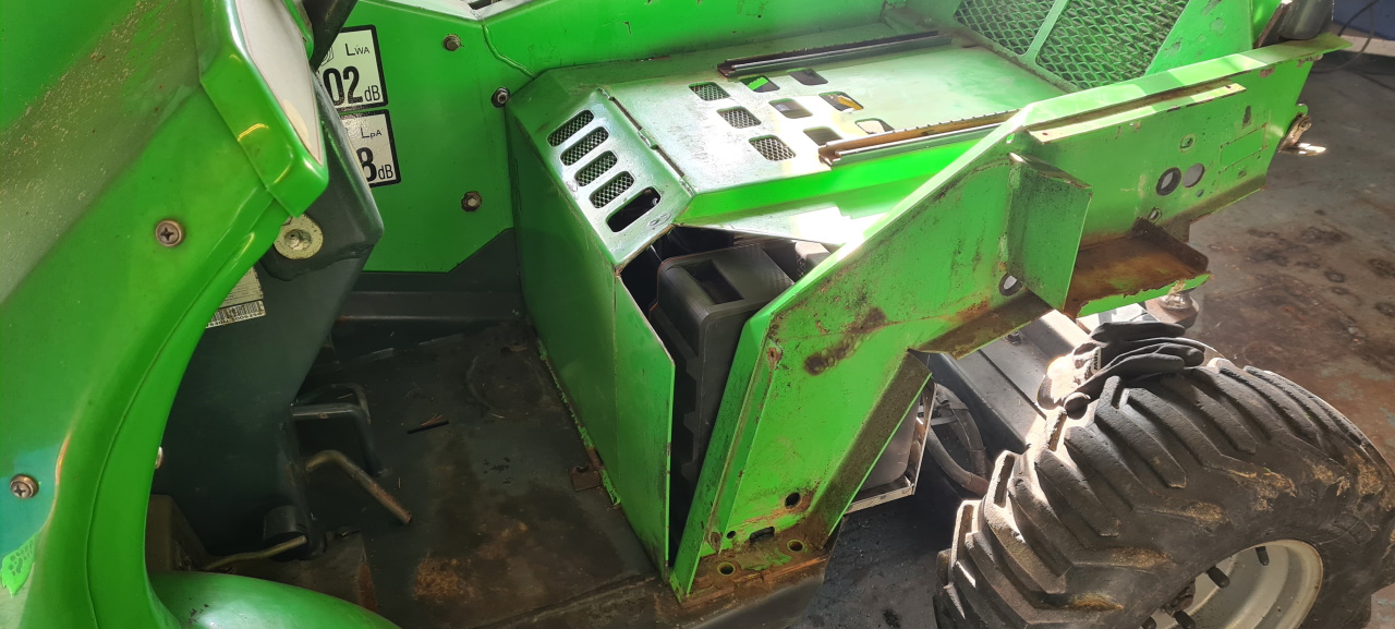
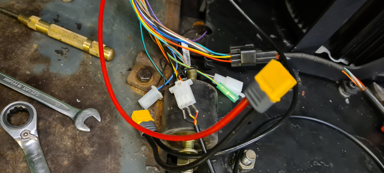
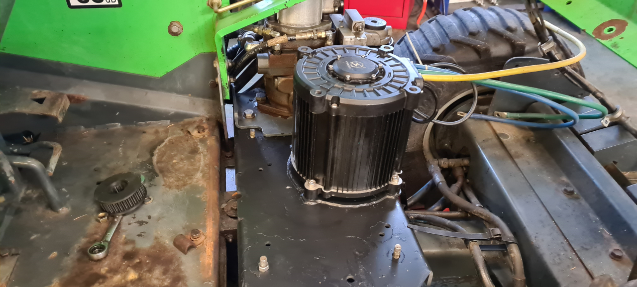
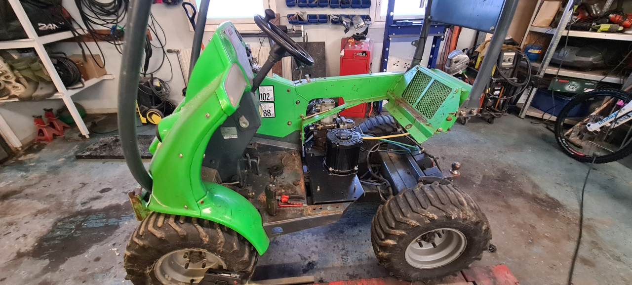
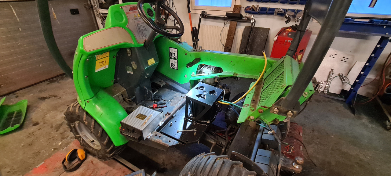
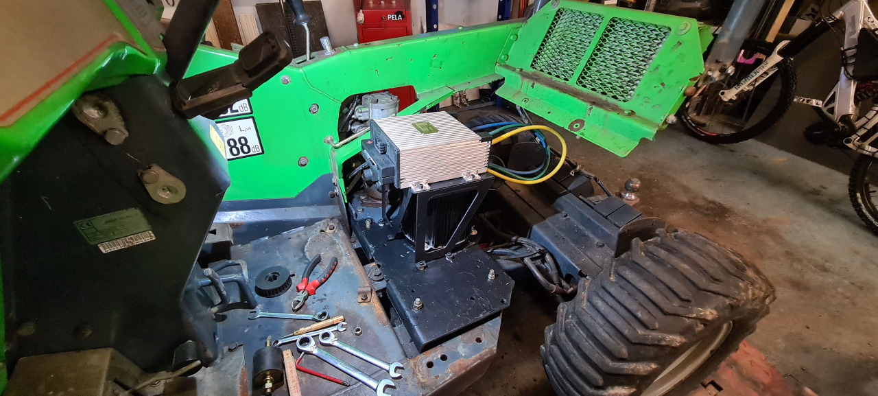
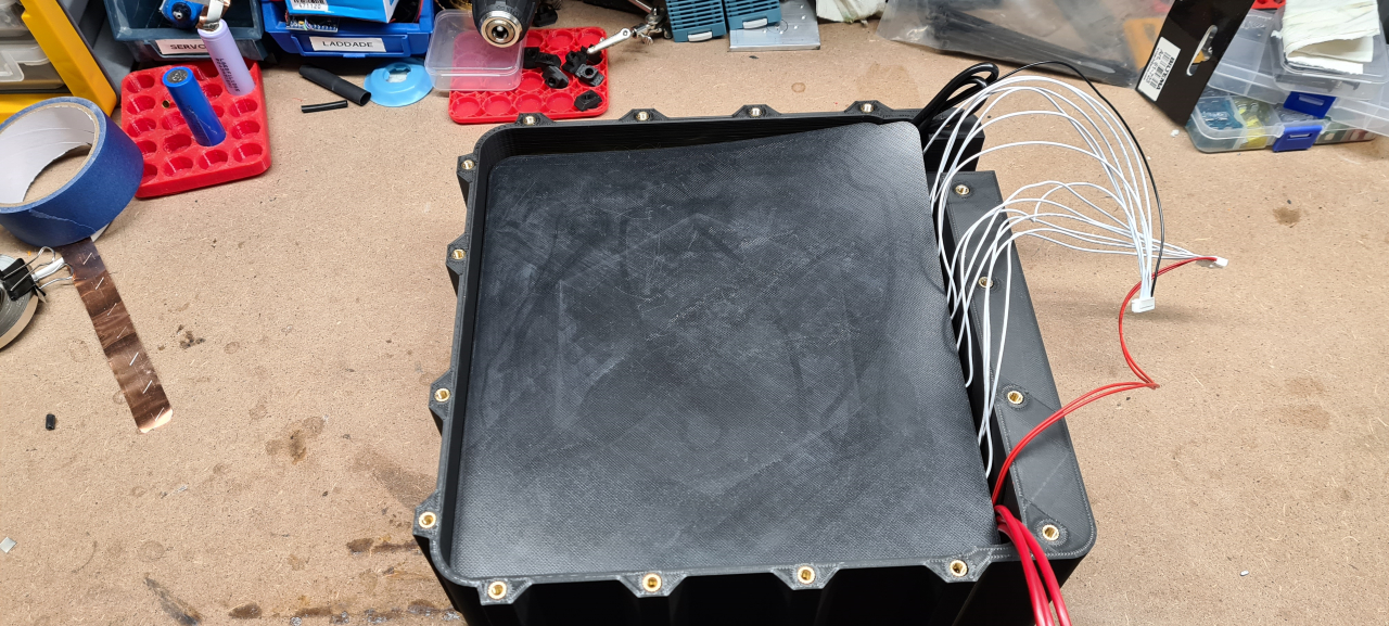
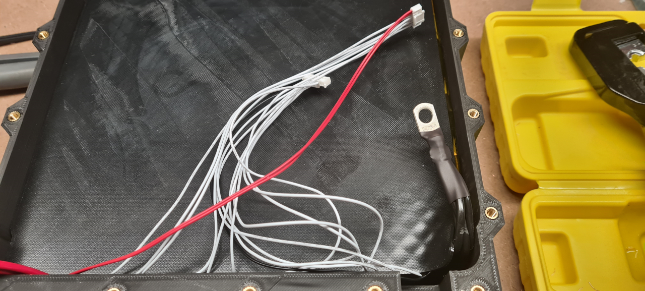
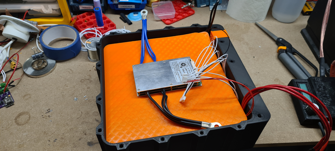
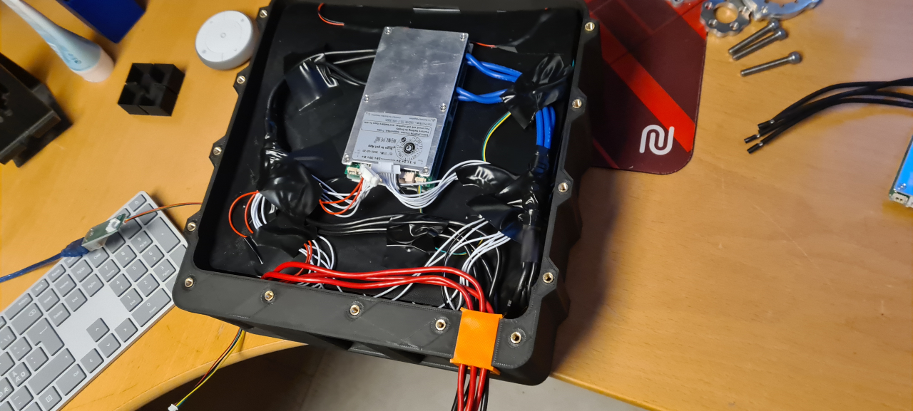
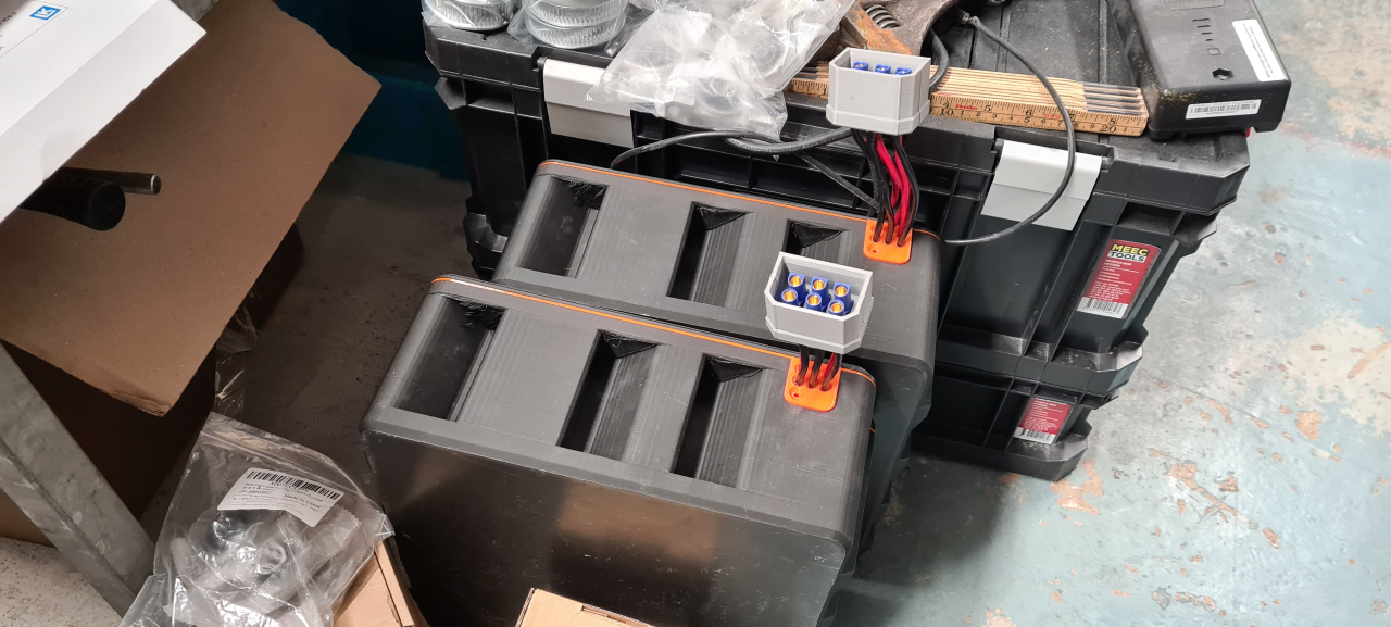
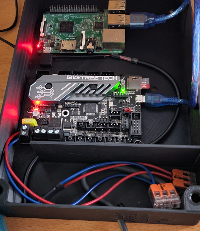
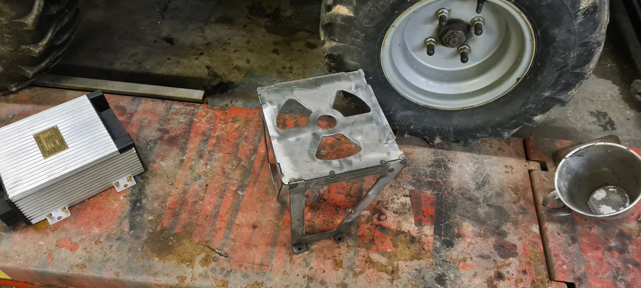
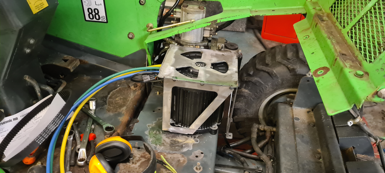
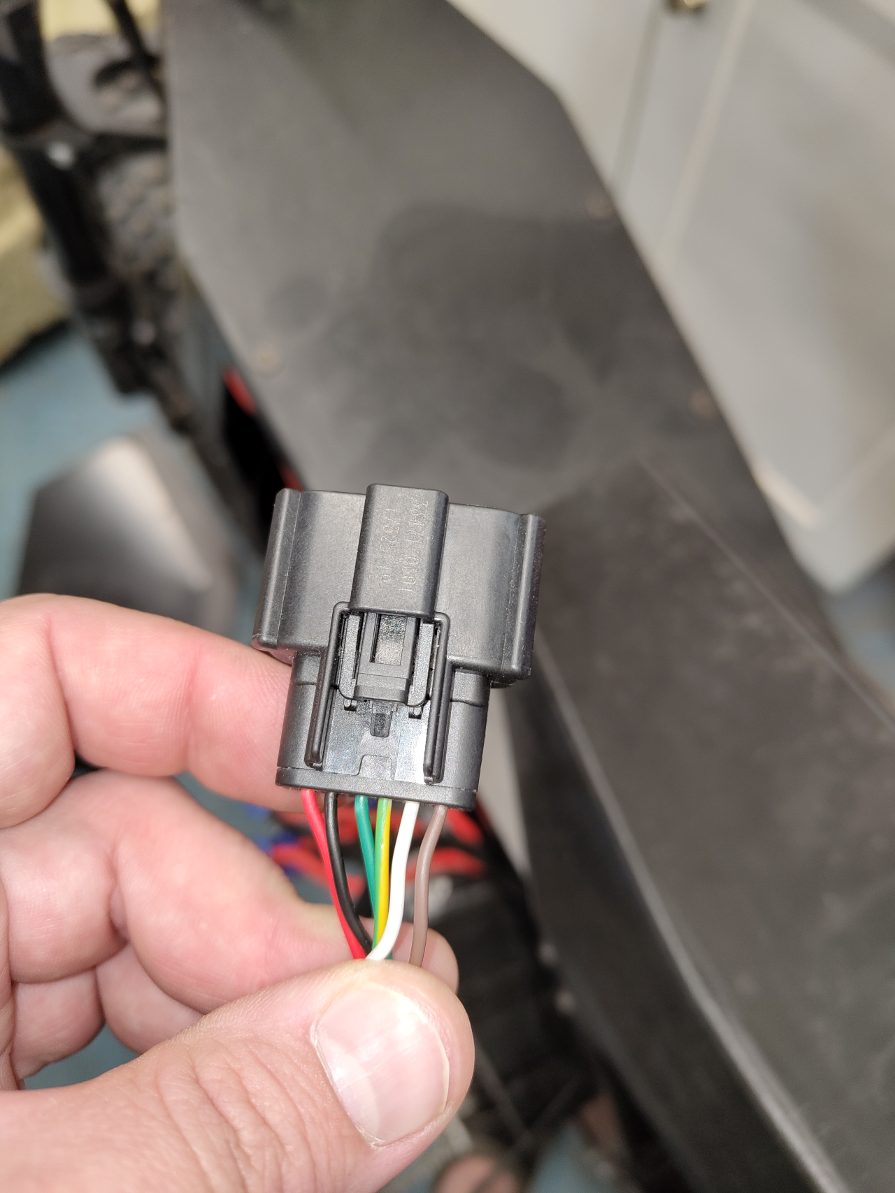
I opted to mount the controller under the seat instead of in the motor well. There it’ll be a bit more protected and it makes for a cleaner installation.. there is however far to much wire in the engine bay..
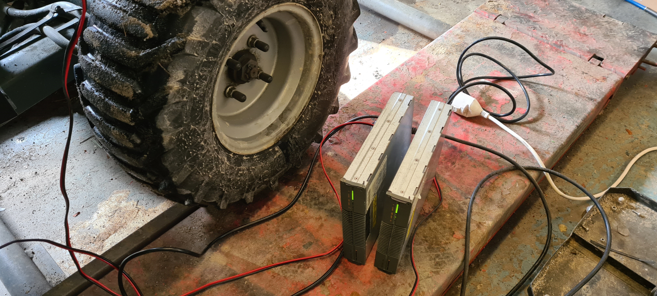
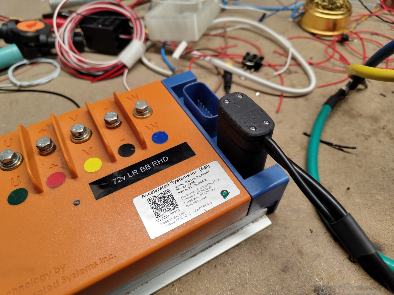
After having connected everything and made a new battery tray to fit an extra battery pack, the motor didn’t run. I loaded the correct settings file and modified it to fit the Avant, but the motor just jerked and sounded real bad and the controller had warnings about the hall sensors..
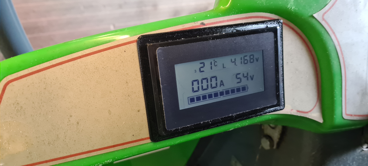
One reason I wanted to run the XXL motor with hall sensors was to be able to use the ”Speed” setting on the control algorithm. This would let me choose the RPM and the controller would adjust the current to stay at that RPM no matter the load. However, what I didn’t know..
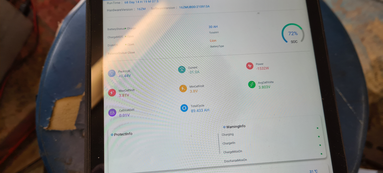
SO – while having problems with the hall sensors causing the controller not to be able to sense the speed it was running I set speed mode without setting the switching frequency and the bluetooth connection I’m using to configure the controller simply crapped out.
I couldn’t connect to the controller, and the controller wouldn’t run. 😀 *yey*
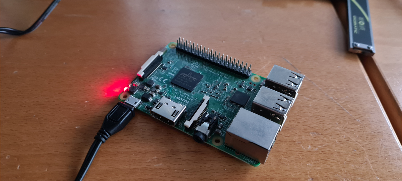
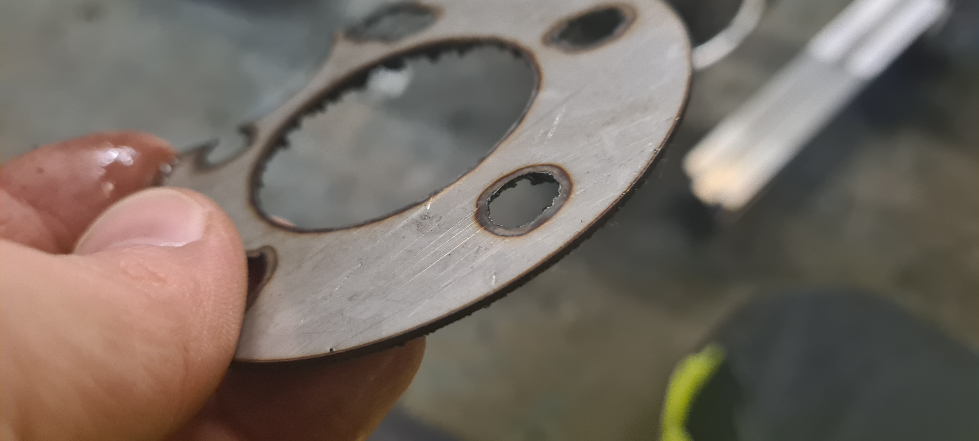
To solve this I had to remove the controller to get it into my office to connect it physically using RS232 to my computer. From there I could, with a lot of help from ”Mr High Voltage” from the High Voltage discord, restore the Switching frequency, the control mode and the bluetooth baud setting. Having measured the hall sensors I figured I had just switched two cables, an easy mistake to make especially when all the other motors I have have custom wire looms that I’ve made myself:
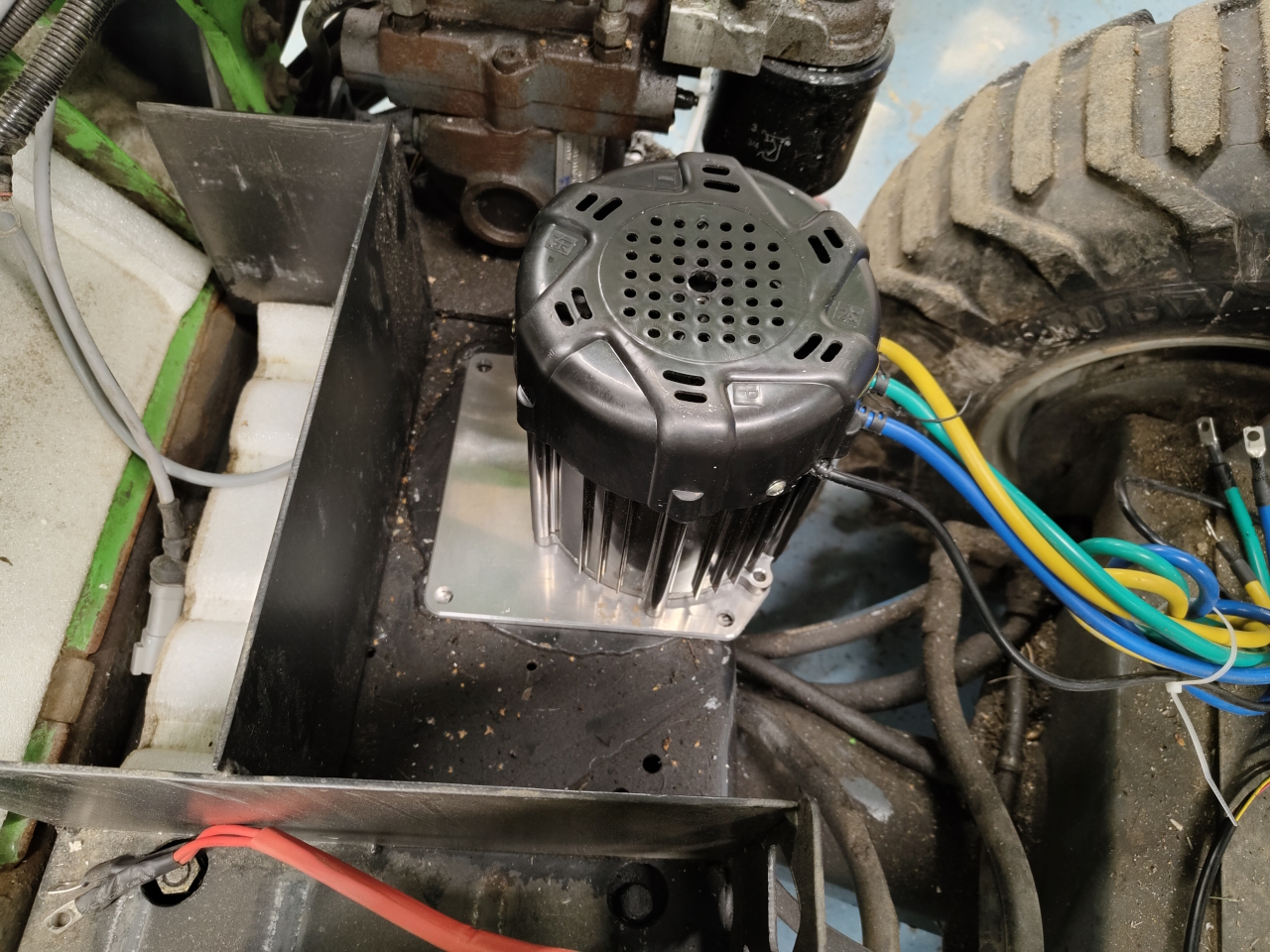
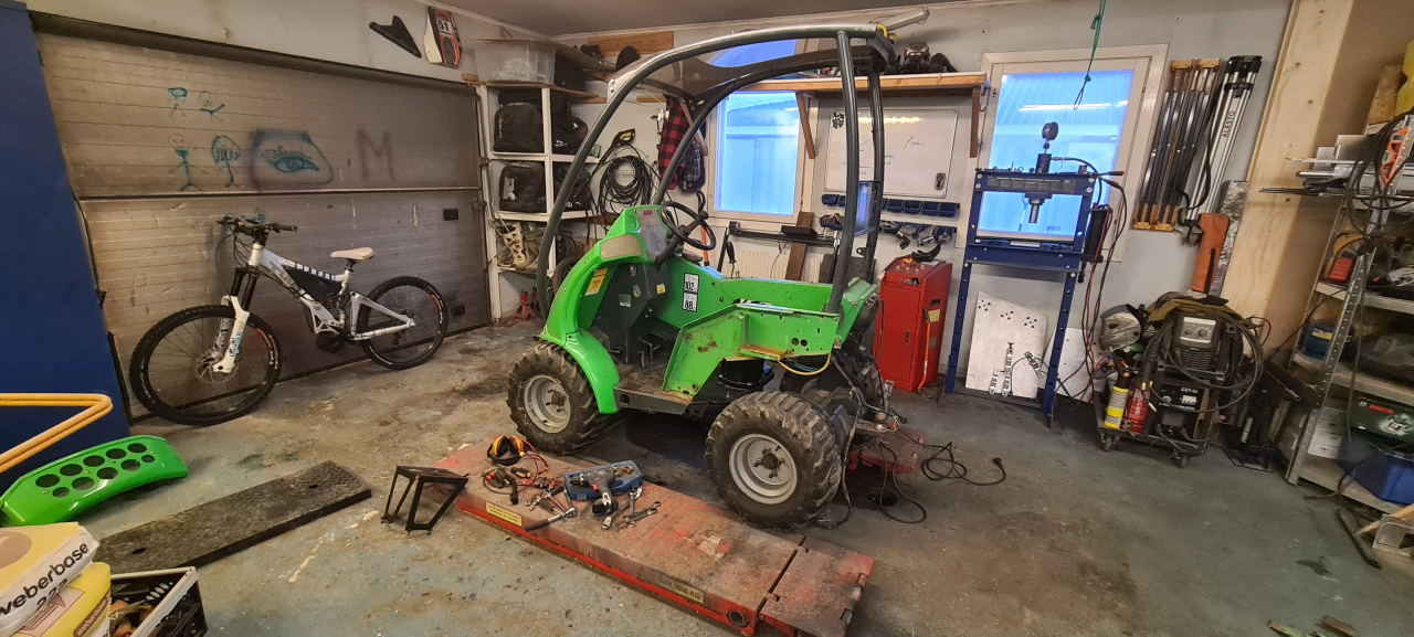
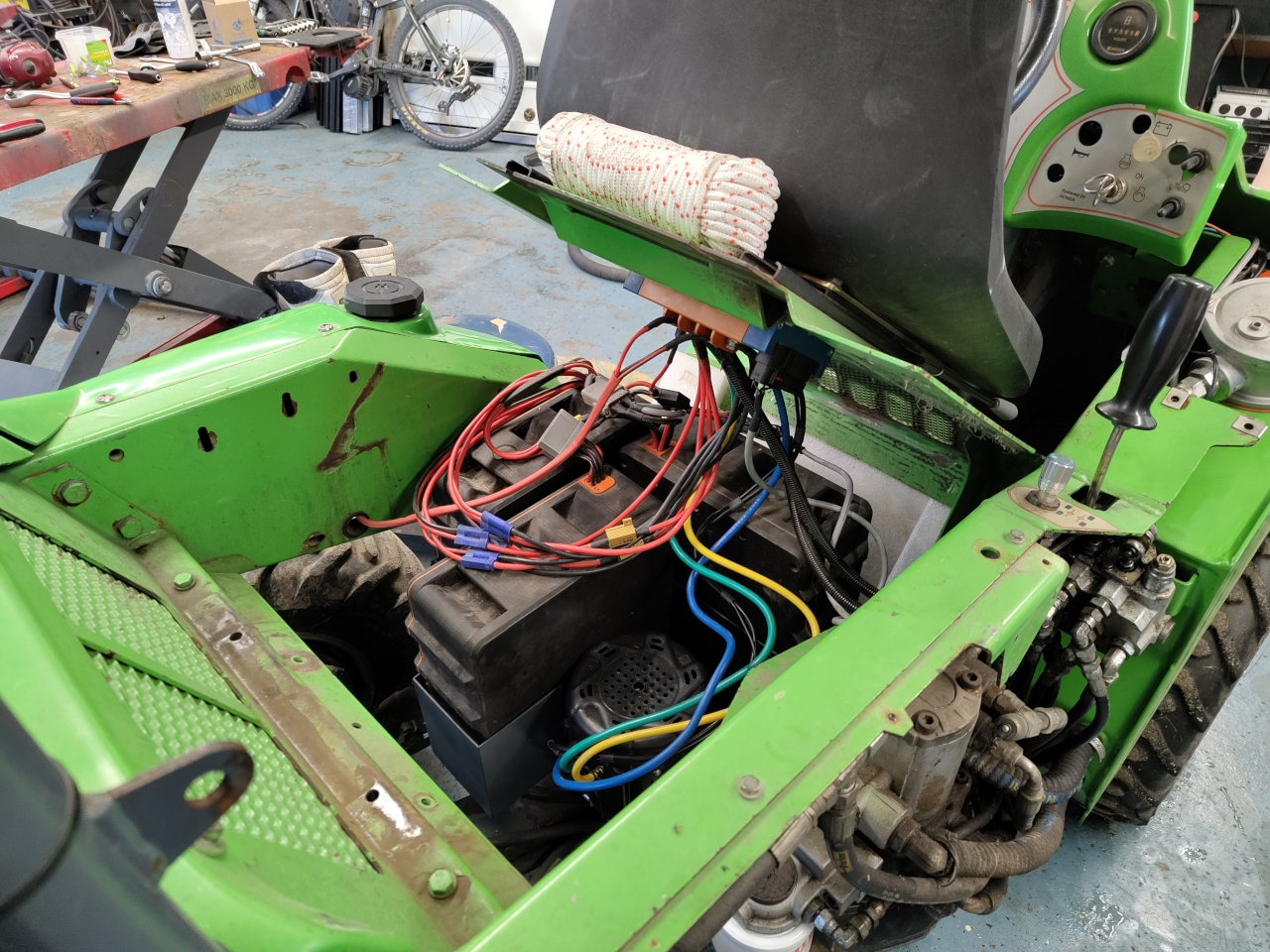
After a bit of rejoicing at the revelation that I hadn’t bricked the controller I put everything back on the Avant.
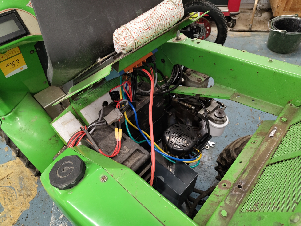
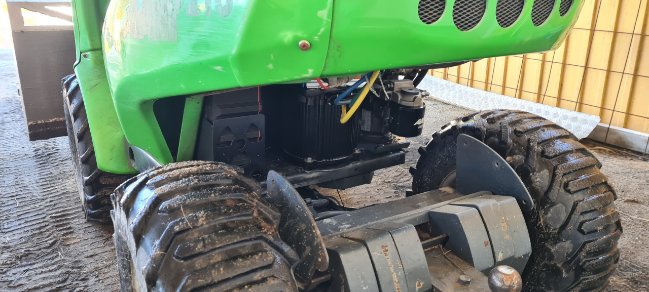
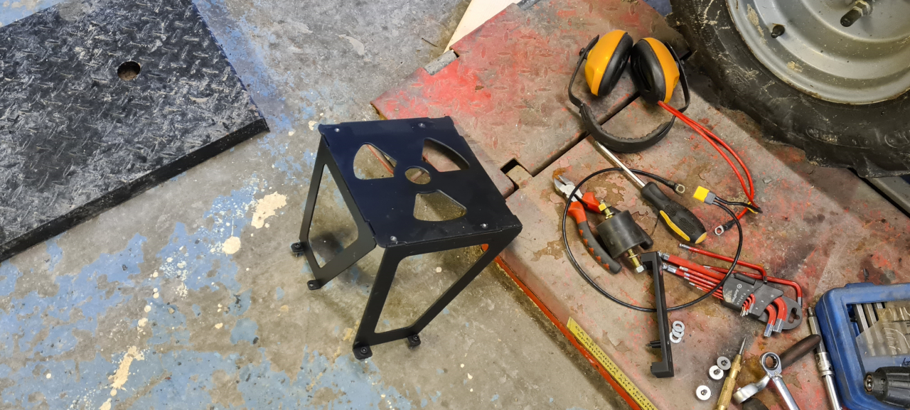
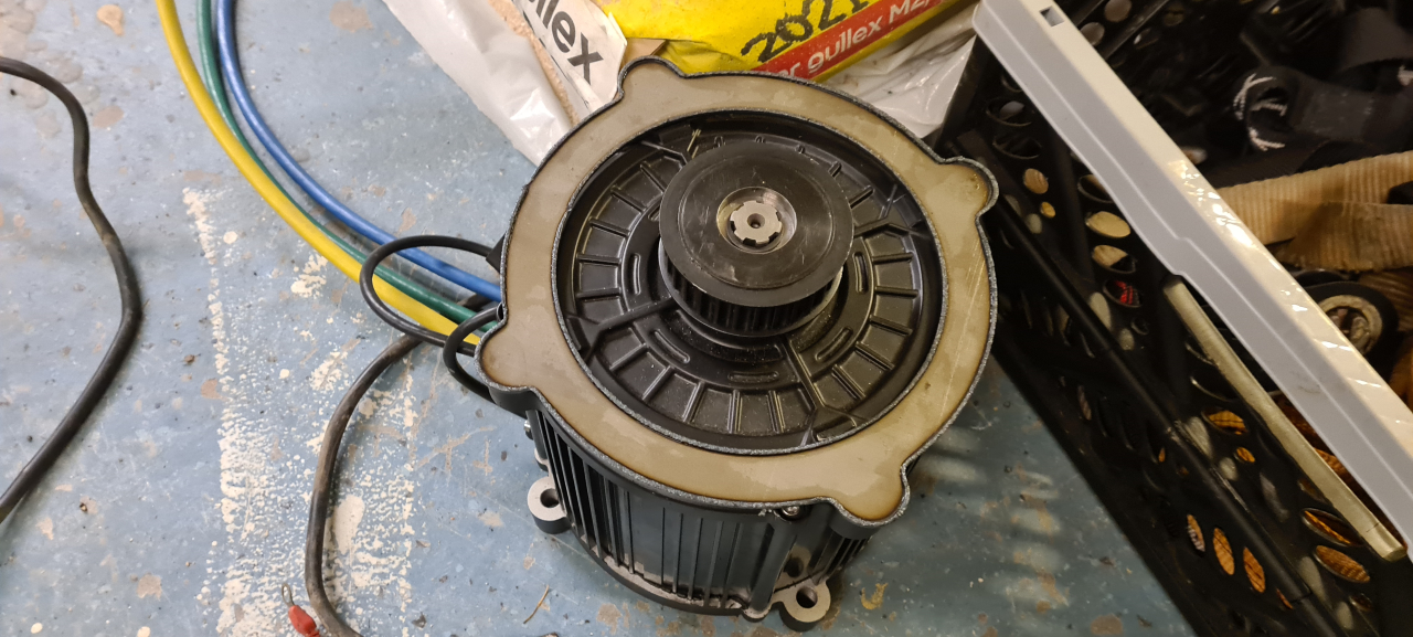
I shortened a few cables and tidied the wiring up as much as I could. Fixed a small leak on the hydraulics, made a washer to fit the belt wheel on the motor as it sat too low and touched the bottom plate of the machine and then the motor just spun like a kitten.
It feels like this motor is a much better fit for the avant. Even with the smaller belt wheel I get more RPM so the machine moves faster. It’s got a cooling fan so it can hopefully stay cool and with room for an extra battery pack I’ll be able to remove the snow from the driveway with volts to spare. 🙂
The only thing I’ve got left to do now is replacing a few joint shafts to get it a little less sloppy, and then the FUN project will start.
TBC