Rear frame, shock- and motor mount

So, it’s been a while since I updated the project but it’s been a slow progress.

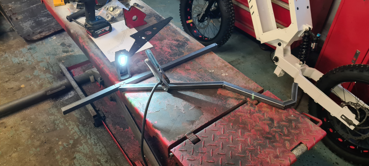
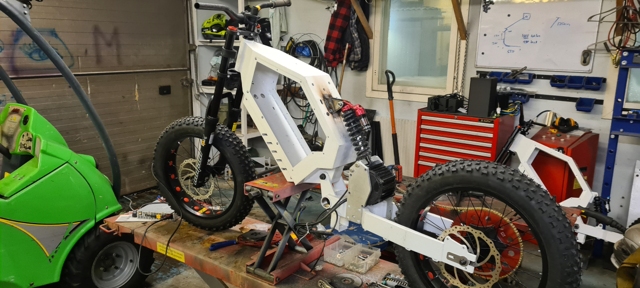
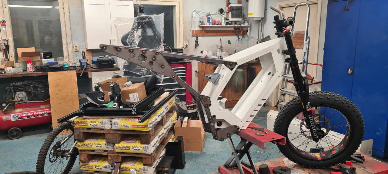
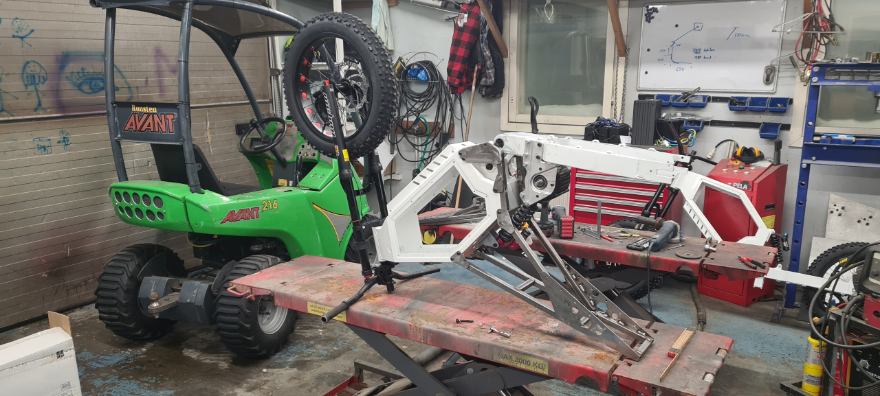
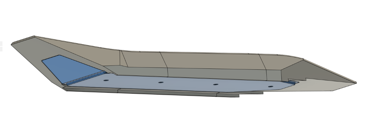
Started by building a mockup for the subframe to test fitment and how it’d look on the frame.

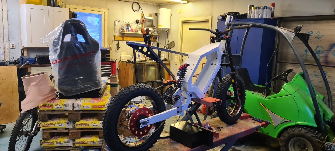
I’m pretty happy with how the mockup looks and fits on the frame, and it seems to be sturdy enough and kind of not too heavy (this isn’t going to be a super light-weight bike anyhow) so, on we go.

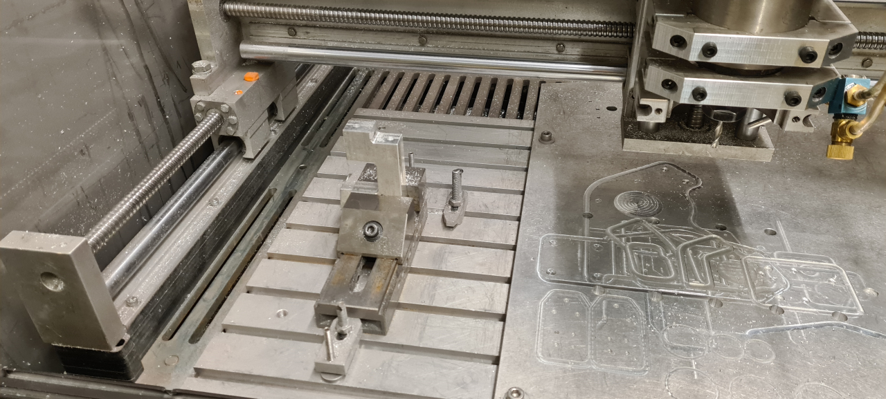
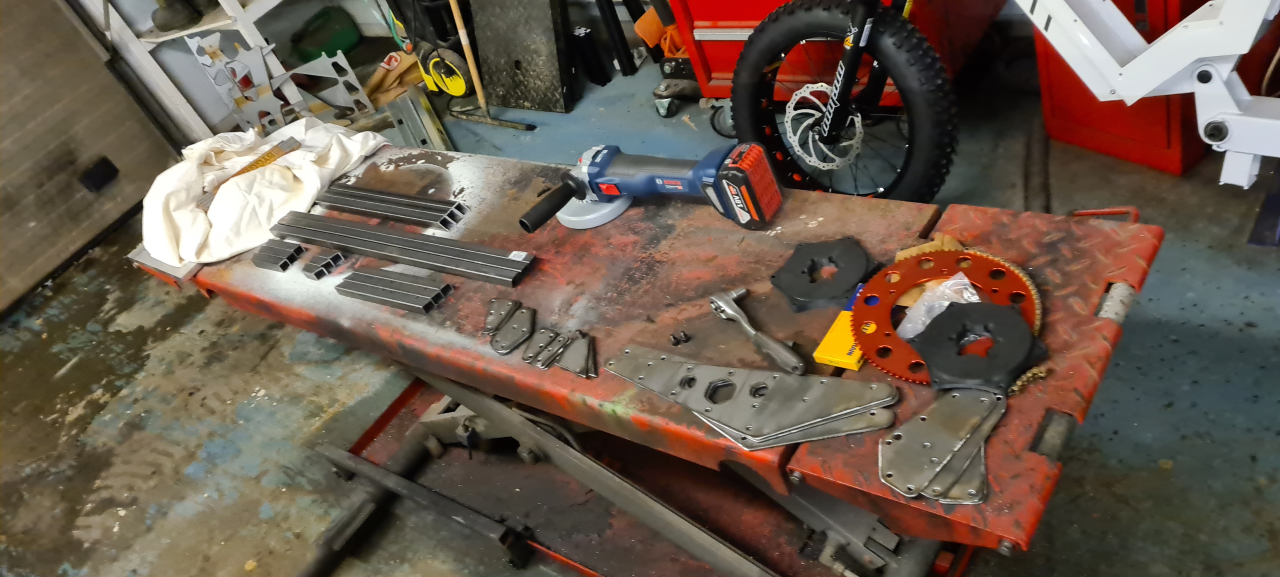
After having upgraded the CNC plasma with a better Z-axis it’s good to cut steel sheet with pretty good precision, so I cut the brackets needed for making all the subframe parts from 2mm steel sheet.

The result is pretty awesome for a low-cost DIY contraption..

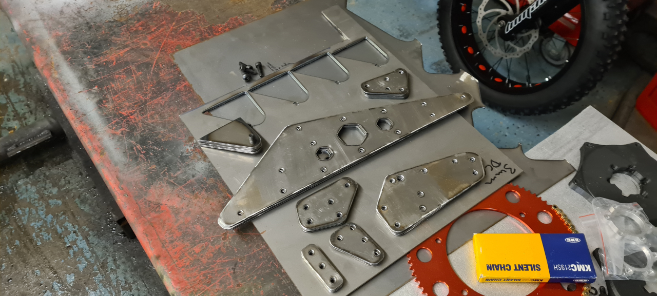
After a little bit of polishing with the grinder the final result is more than good enough.

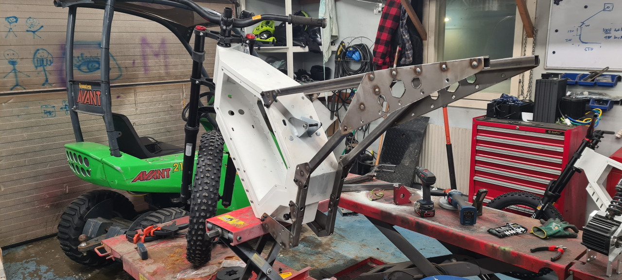
Unfortunately the 20×20 square tube mounted on the side of the frame interfere with the rear shock, the way I were planning on mounting it so I needed to come up with a new bracket.
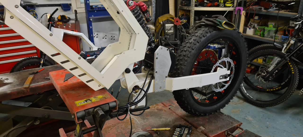
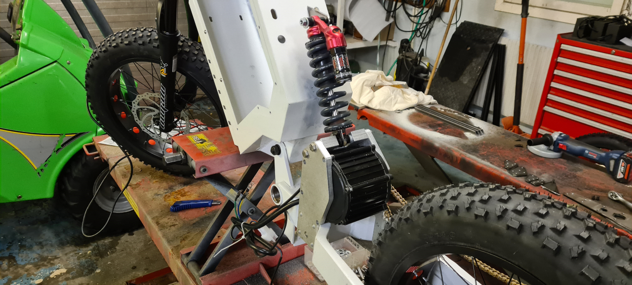
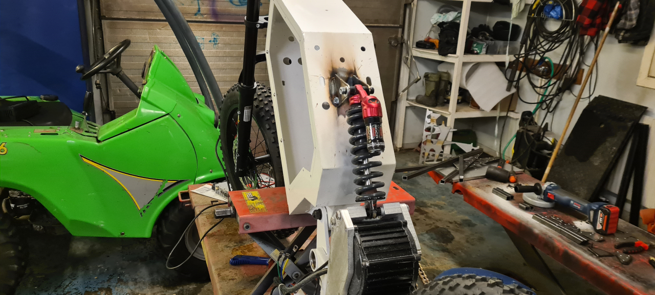
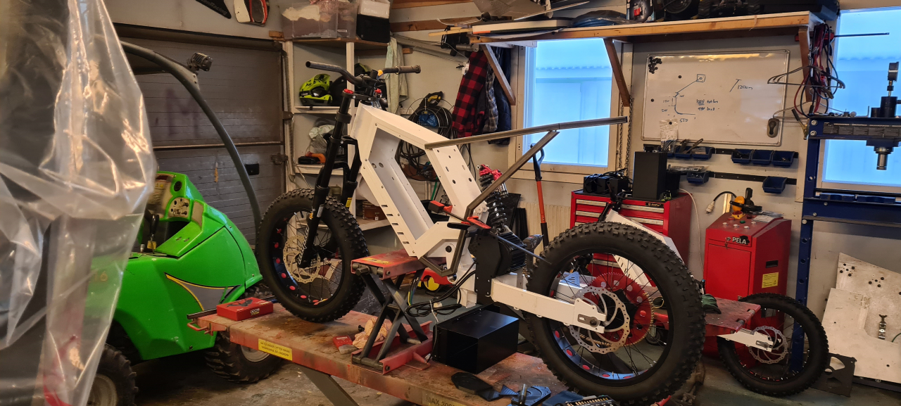
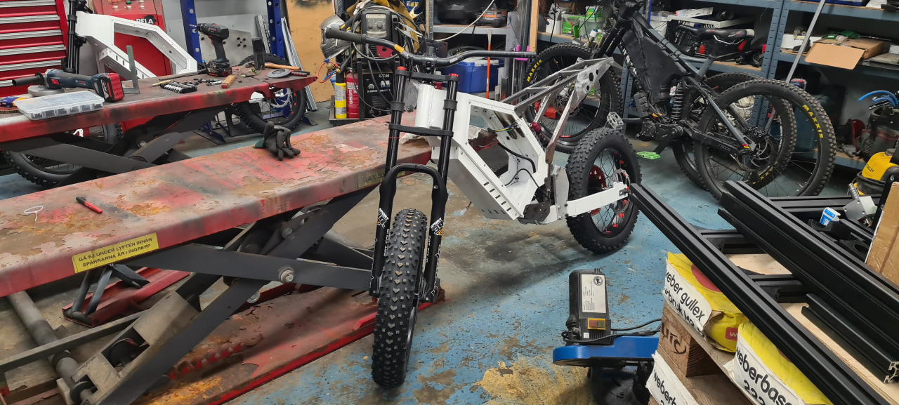
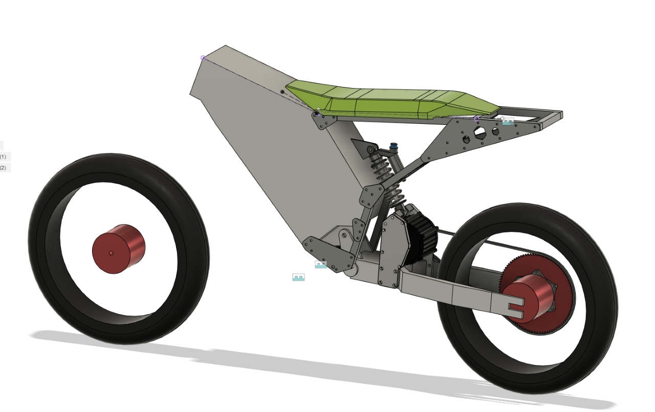
I milled the rear mount/cover for the motor from 13mm aluminium and secured it to the frame.
Then I made a bracket from 20mm aluminium to support the motor mounts and double as the lower mount for the rear shock.
Bolting it all together with M8 bolts, adding a bolt in the lower “ear mount” on the motor too, everything sits solidly in place.

So I cut a couple of “ears” from 3mm steel sheet and welded the upper shock mount onto the frame. Now the stance of the bike is decided and it feels pretty OK.

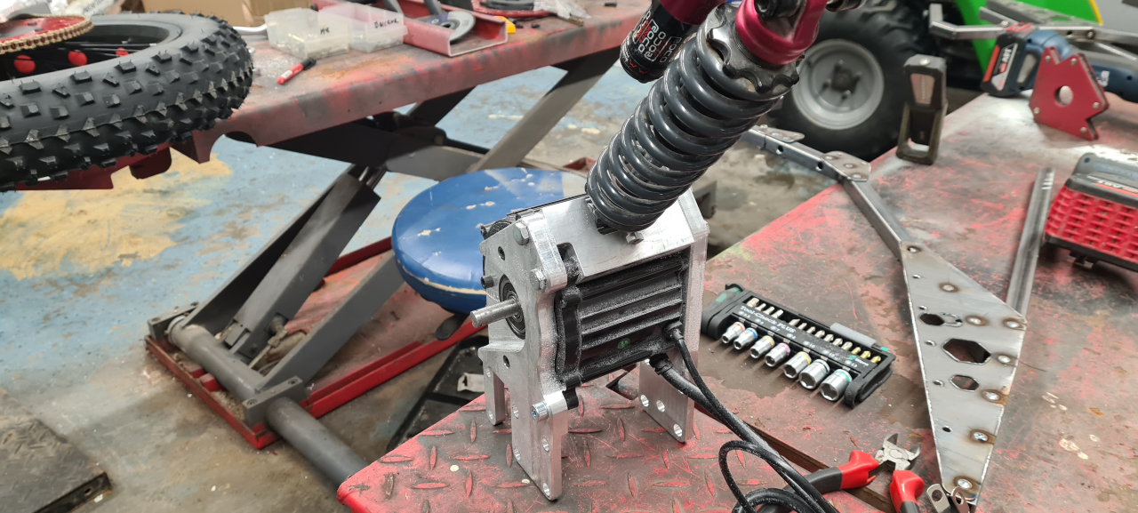
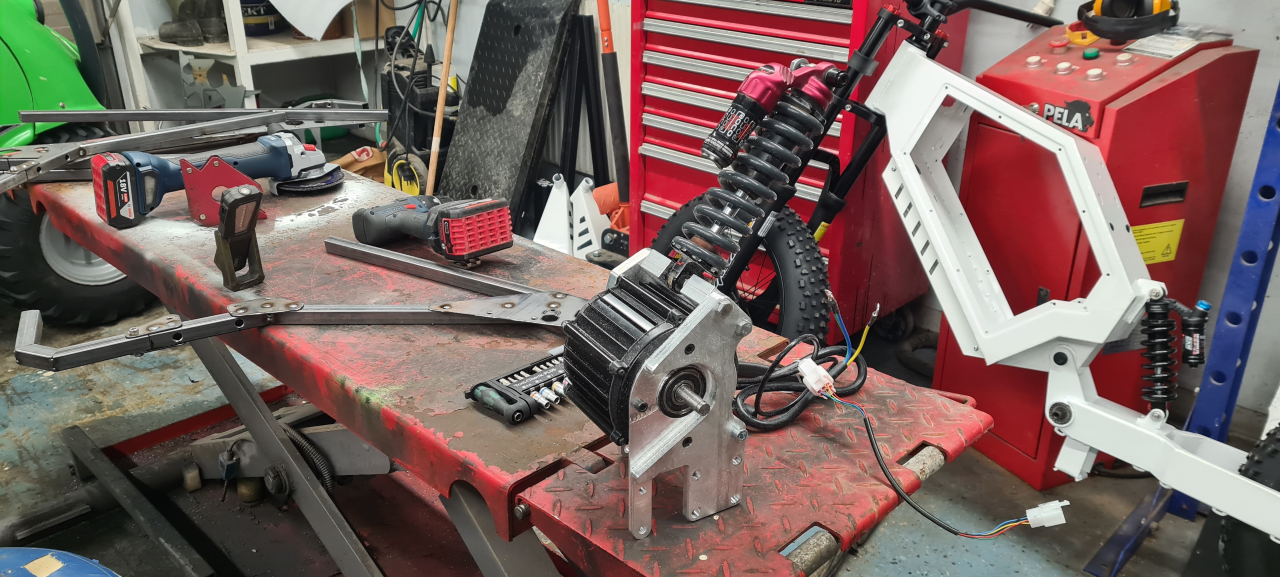
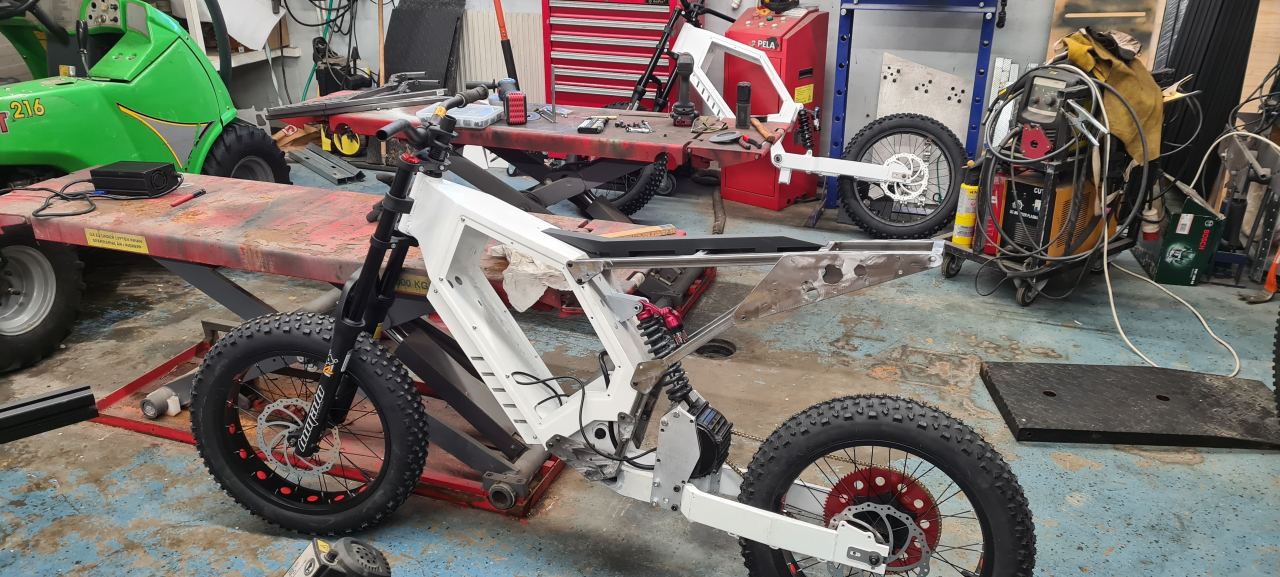
The motor/shock mount is easily removed from the bike with just 9 M8 bolts. This is great for service and painting later on. If I may say so myself it looks frekkin’ awesome! 😀

Making the subframe

I decided to make the subframe from 20×20 square tubing as it’s strong enough, not too heavy, cheap and easy to get.

I started with printing paper templates from the CAD drawing and cut tubing to size..
I drilled the holes for the mounting screws where needed in the subframe and now had enough parts for 2 complete setups.
Brackets and frame tubing for the 3 subframe sides needed on top of the mockup I’ve got on the bike already.

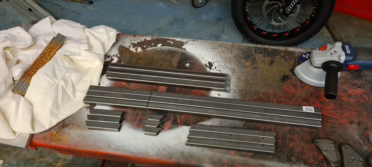
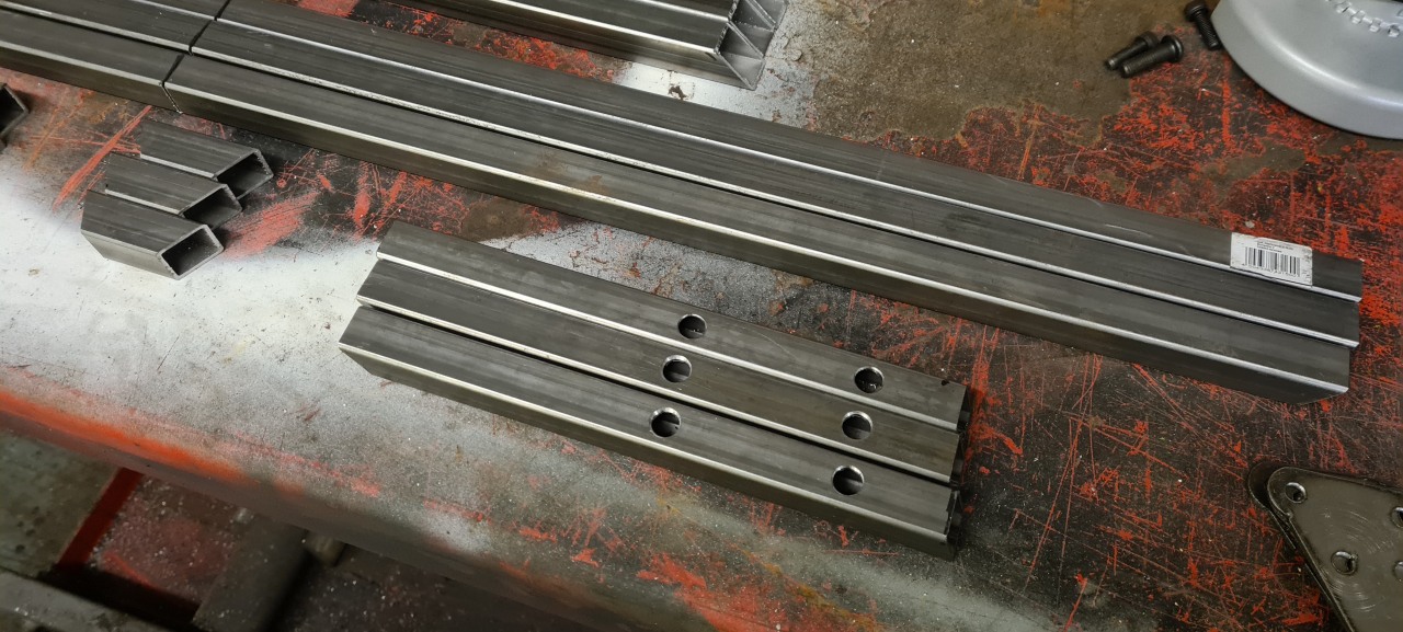
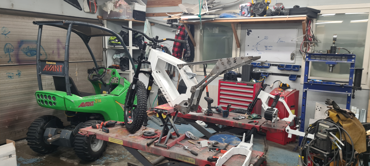
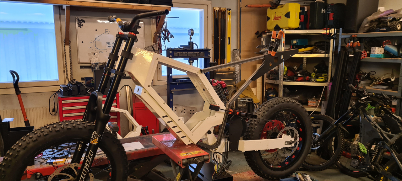
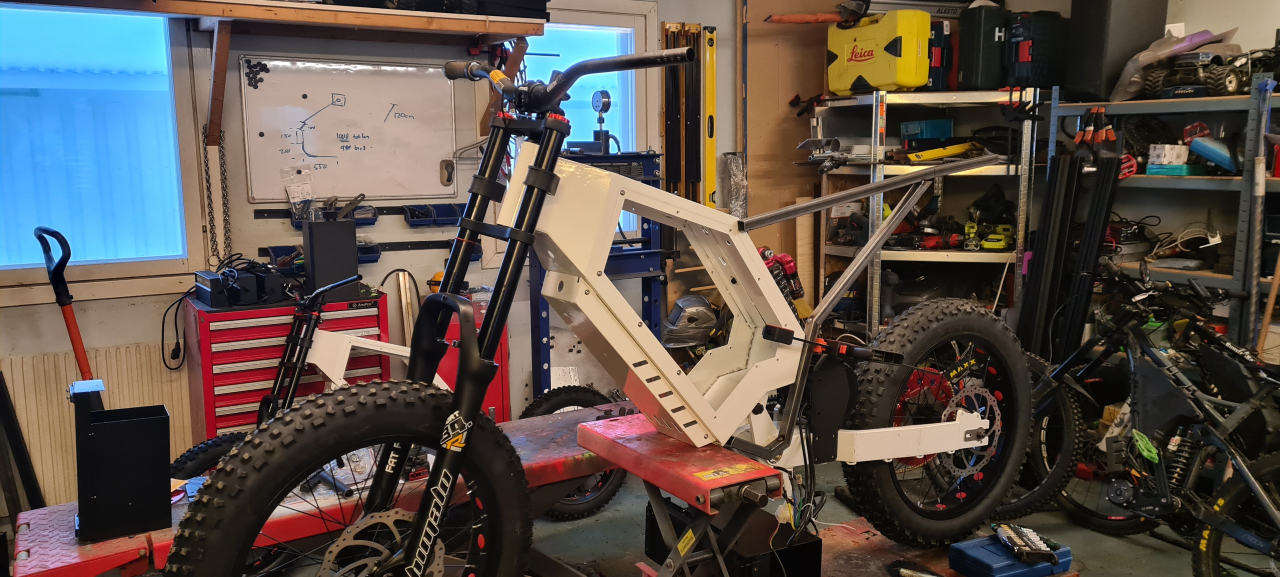
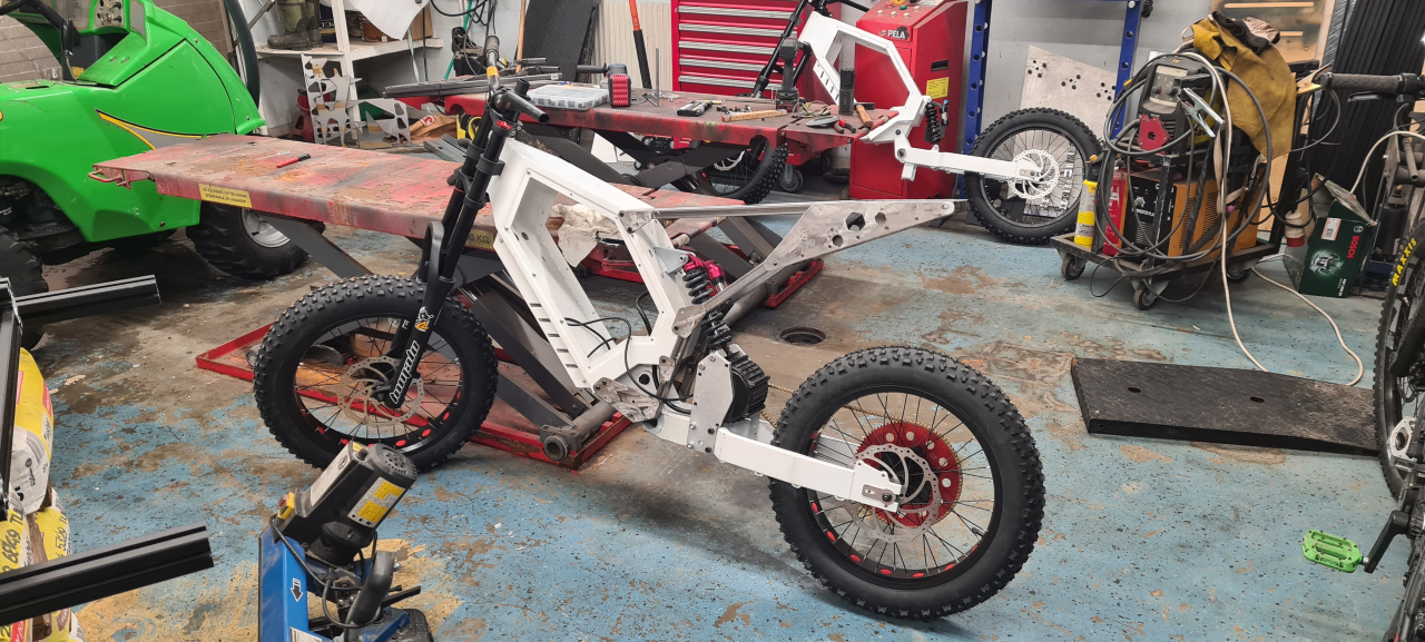
When this was done I just had to quickly weld everything together, drill and tap the mounting holes on the frame and make the joining parts for the subfrtame. The subframe goes under the bottom of the frame to be able to fit the footpegs.

Now I can fiddle with the bike “bicycle style”, putting it upside down on the workbench. This makes it a lot easier to fiddle with the motor mount and chain tensioner and so on. 🙂
It looks OK and feels OK to sit on too.

Battery and seat

So, that’s about where we are for now. What’s left is a few fairings, the seat, battery and electrics.. (And the brakes of course)

I made a quick CAD of a seat to see what it’d be like. I’m printing the seat core from PETG plastic and the seat cover from TPU. Experimenting a bit with getting the cover cushioning enough so we’ll see where we end up.

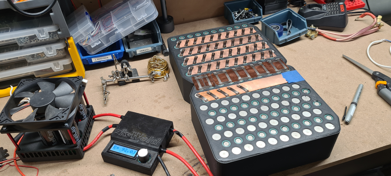
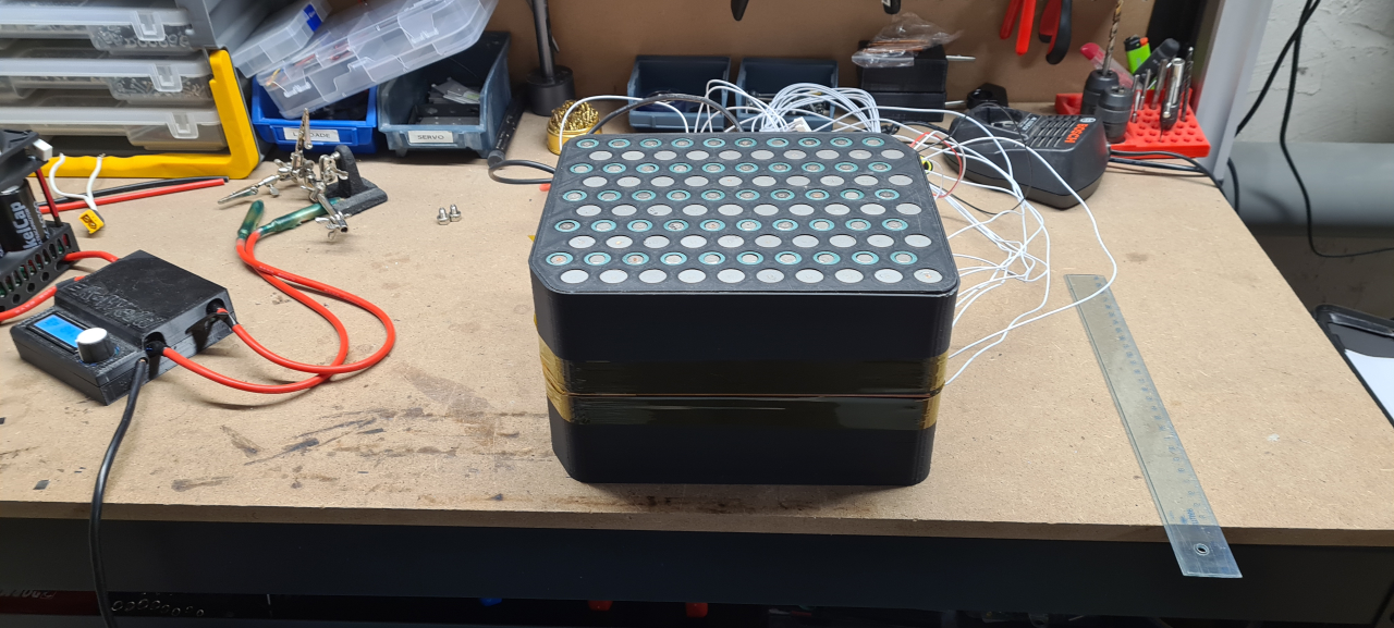
While the 3D-printer is making seat parts I’m finishing up the battery.

Since this battery will have to push north of 200A I’m building it as a copper/nickel sandwich. The configuration is 20s10p, ie 72V nominal. The cells I’m using are Samsung 30T, 3Ah capable of a continuous 35A. The BMS will be a 300A ANT BMS with bluetooth capability. In the picture you can see my new kWeld setup with kCap ultra capacitors. It works flawlessly and gives much more consistant welds than my car-battery setup did. Super happy with this.
To fit the pack in the box on the frame I’m making it fold, so at the moment I’m welding the outer sides and soldering the BMS wires to it. It’s going to be a tight fit but if it gets too wide I’ll just make new brackets and covers for the frame box, so that’s going to be alright.

Well, that’s all for now. To be continued.

Lämna ett svar

Din e-postadress kommer inte publiceras. Obligatoriska fält är märkta *

Säkerhetsfråga * Time limit is exhausted. Please reload the CAPTCHA.