So, after testing the bike for a few trial runs it stopped working. Connecting to the controller I got an error saying ”Post static gate test” which usually means there’s a problem with the controller having a mosfet fused to ground or the postitive terminal.
So, a bit displeased I started taking the bike apart but before putting in an RMA I decided to test another controller I’ve got sitting around, and got the same error with that one.. so, the problem seemed to be with the motor, which was a bit wierd. Connecting my second motor to the controller confirmed that the motor was the issue since it ran without any problems.
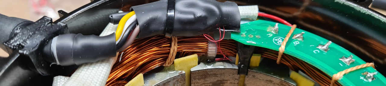
After doing some measuring I was a bit confounded as all the resistances seemed to check out and sure enough when I connected the motor windings to the controller it all worked. However, when I connected the hall sensor array it stopped working again.. Hmm..
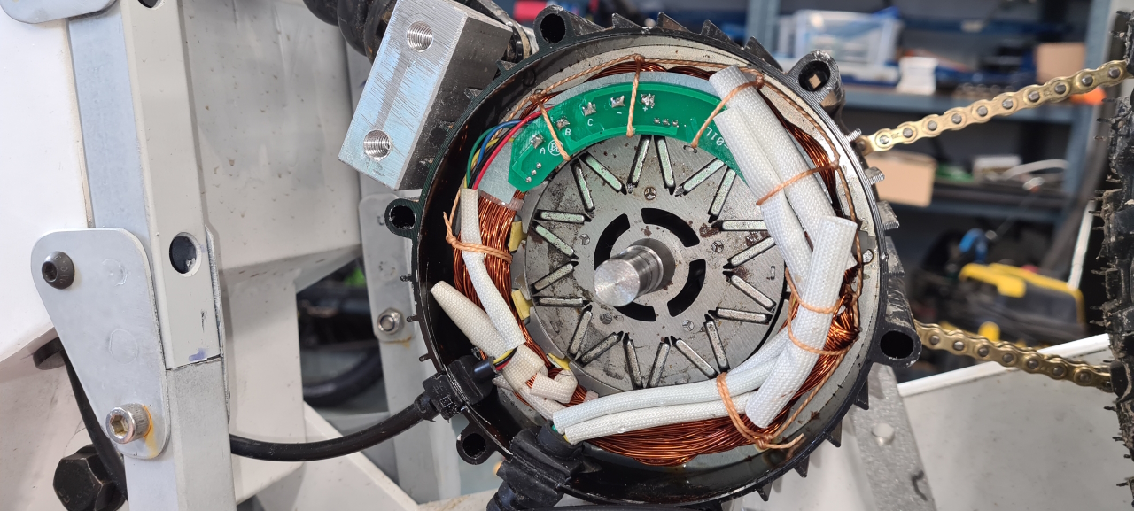
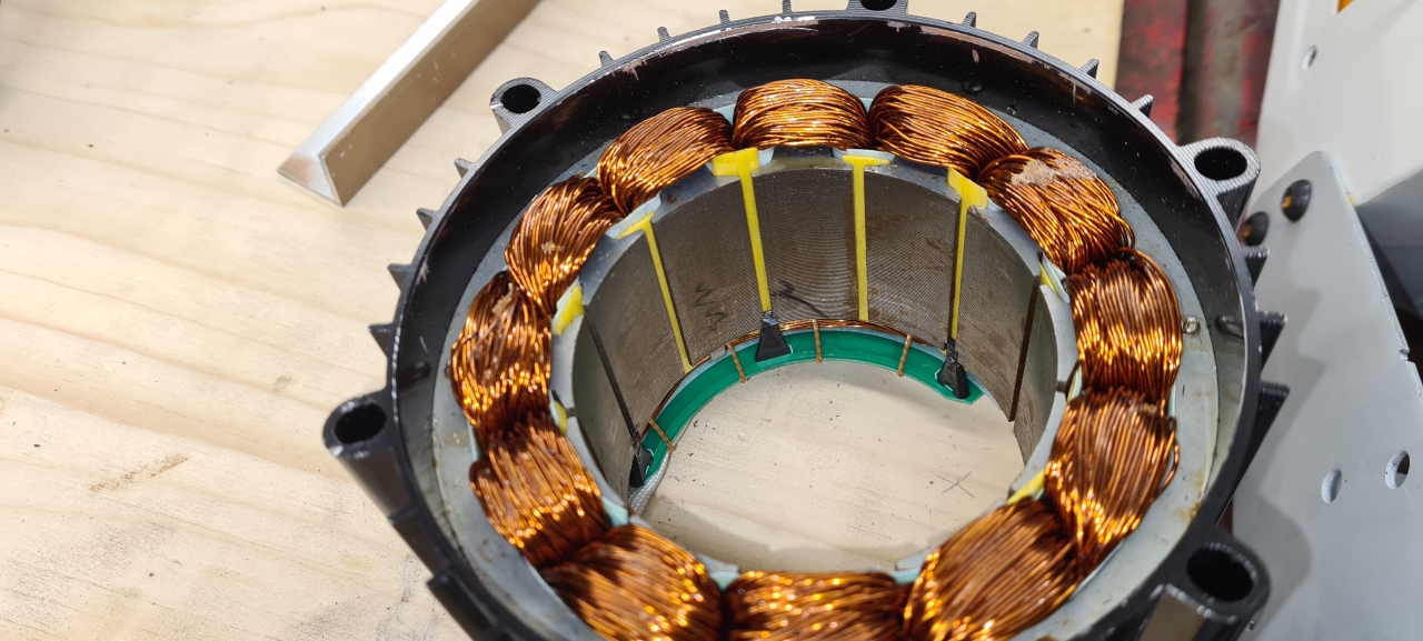
Taking the motor apart the seal that sits between the stator casing and the end bells on the motor crumbled to dust which is probably why the water got in there in the first place.
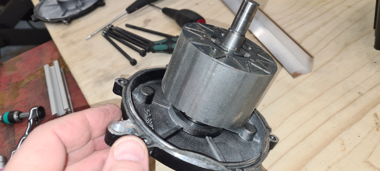
If you get your fingers caught between the stator casing and the end bell on the motor I guess you’d have to leave your fingertips inside the motor. I’m not looking forward to putting it back together again.. I’ll have to come up with some contraption to make it not slam back cause I reckon that’d make the motor self destruct and take half of the garage, both my hands and my left liver with it as it goes…
As I had the motor apart I thought I’d add a thermistor to be able to have the controller reduce power if the motor gets too warm. The Lightningrods motors come with a thermistor if you ask Mike to install one, which I happeded to forget..
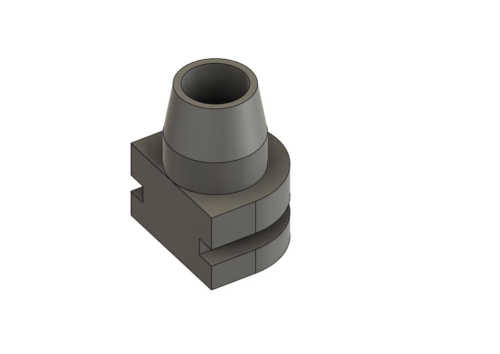
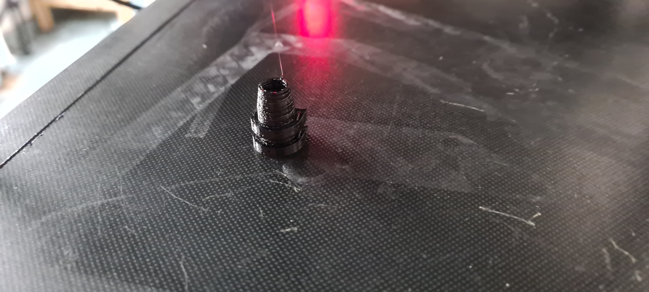
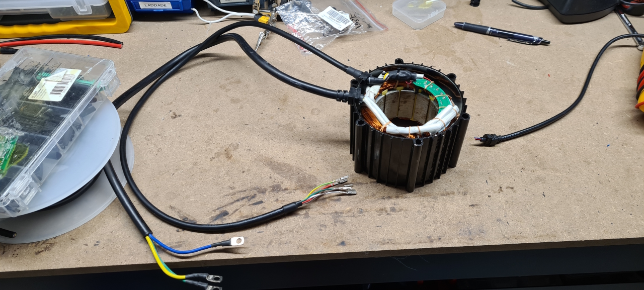
The normal way of adding a thermistor is to make a hole in the case and route a cable from the thermistor to the controller through there but I didn’t like the idea of adding another cable to the motor. Two is enough I think. So I instead opted to replace the 5 lead cable that goes to the motor originally with a 6 lead cable instead. To be able to fit the larger cable I had to make a new grommet for the motor casing though.
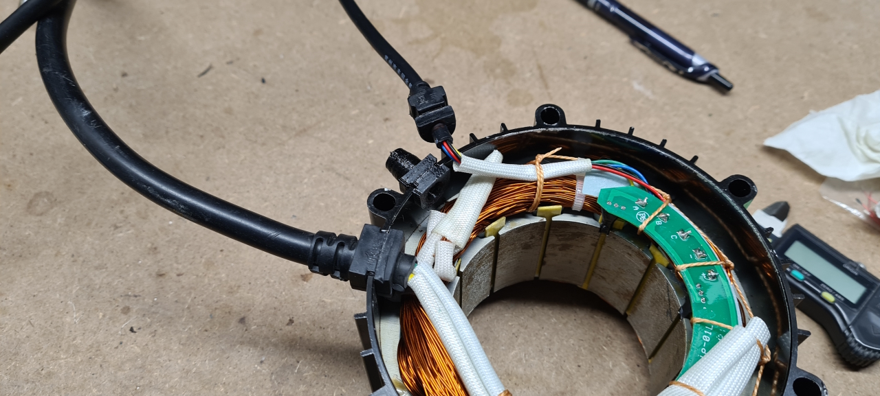
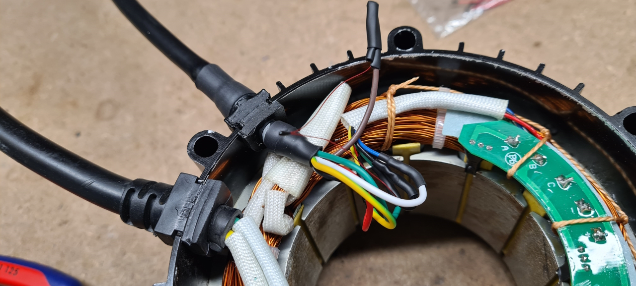
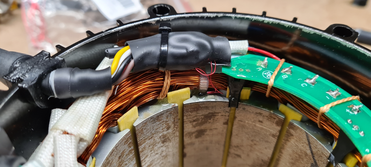
Taking the motor apart I saw that the conformal coating on the hall sensor PCB was missing in part, probably allowing the problem to occur in the first place. I used epoxy to cover the PCB to hopefully make the motor more resilient to failure in the future even though some moisture might get inside.
Well, to be continued..