Battery design, first step
Svara
To be continued..
So, since recovery from the fatigue syndrome is super slow so will updates on the project be. That’s just due to most of my afternoons being spent resting and trying to get the brain to recover. But some progress has been made lately, both recovery- and project wise.
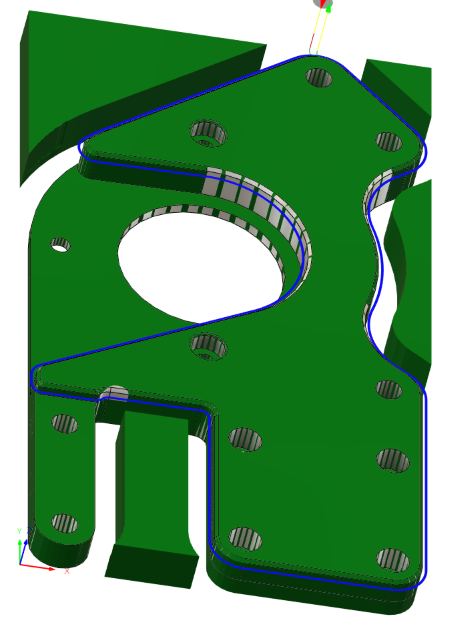
I’ve iterated the motor mounting plate design a bunch of versions and am pretty happy with it. Time to make some proper parts.
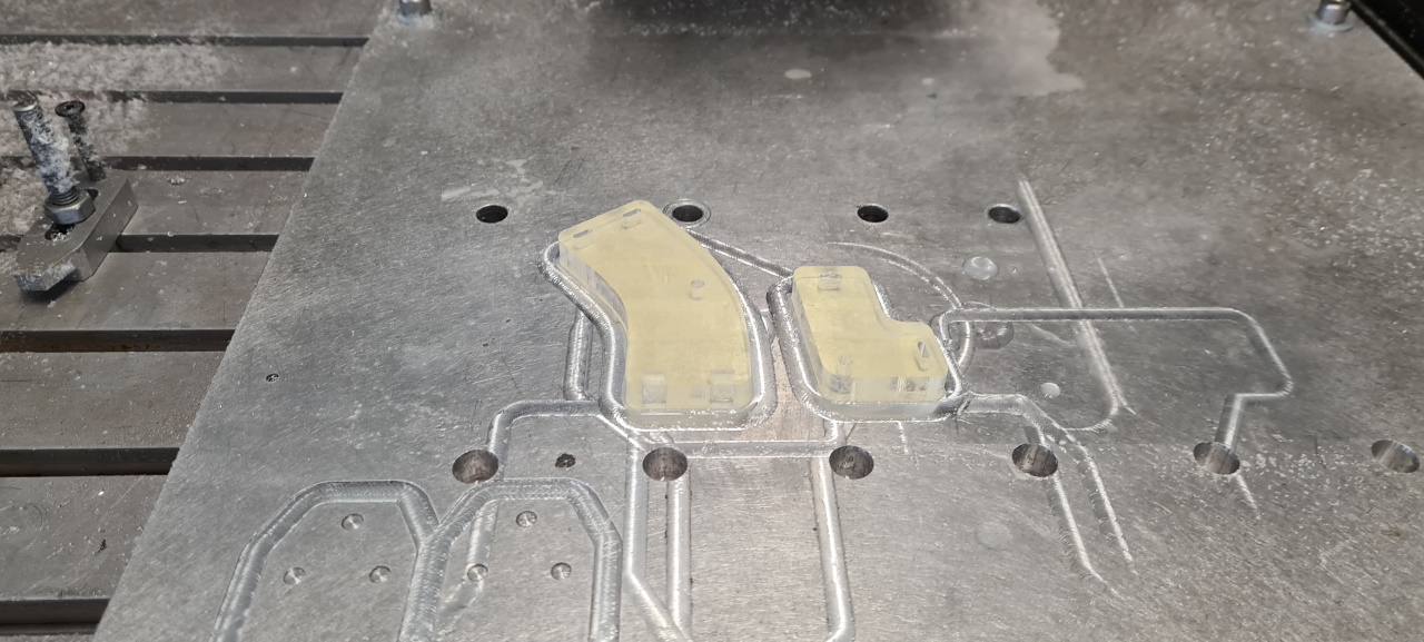
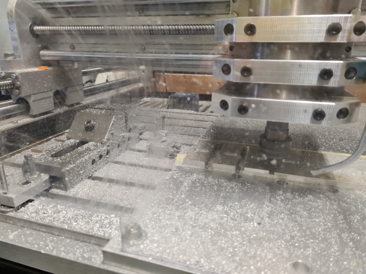
After some CAM-work in Fusion360 I cut some sheet aluminium and got to milling.
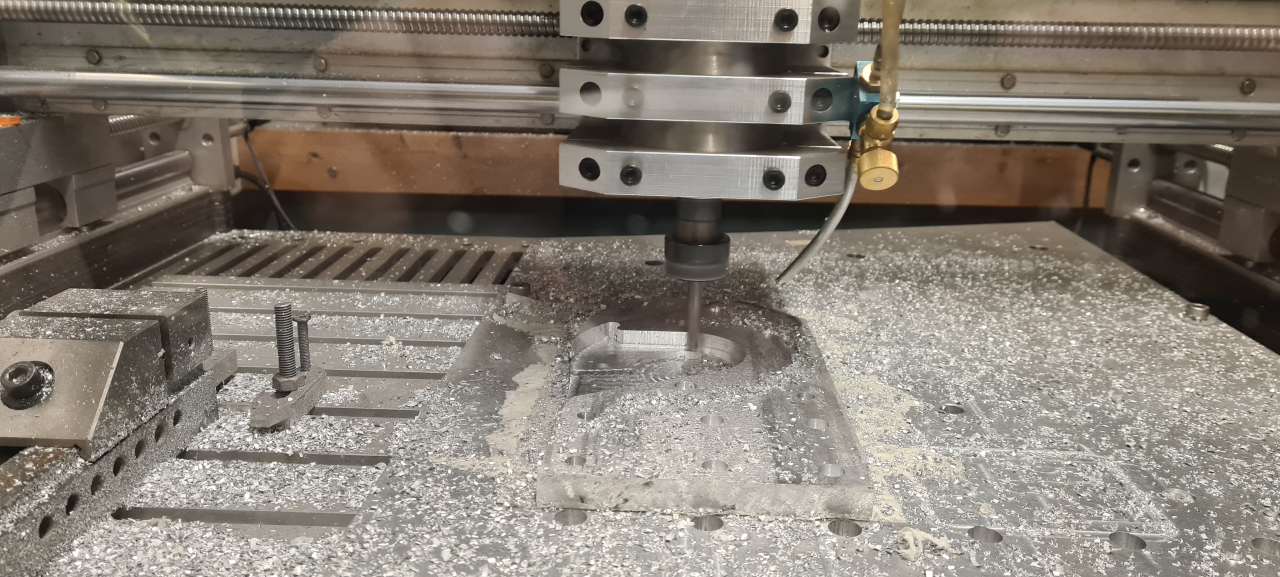
The mill really makes a mess throwing shavings everywhere, but since I built the enclosure at least it doesn’t fill the entire workshop with metal shavings. 🙂
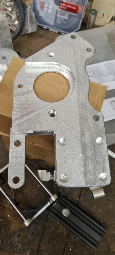
The result when milling aluminium is pretty amazing. This part looks even better IRL than in the pictures and being made from 13mm thick plate it’s super sturdy!
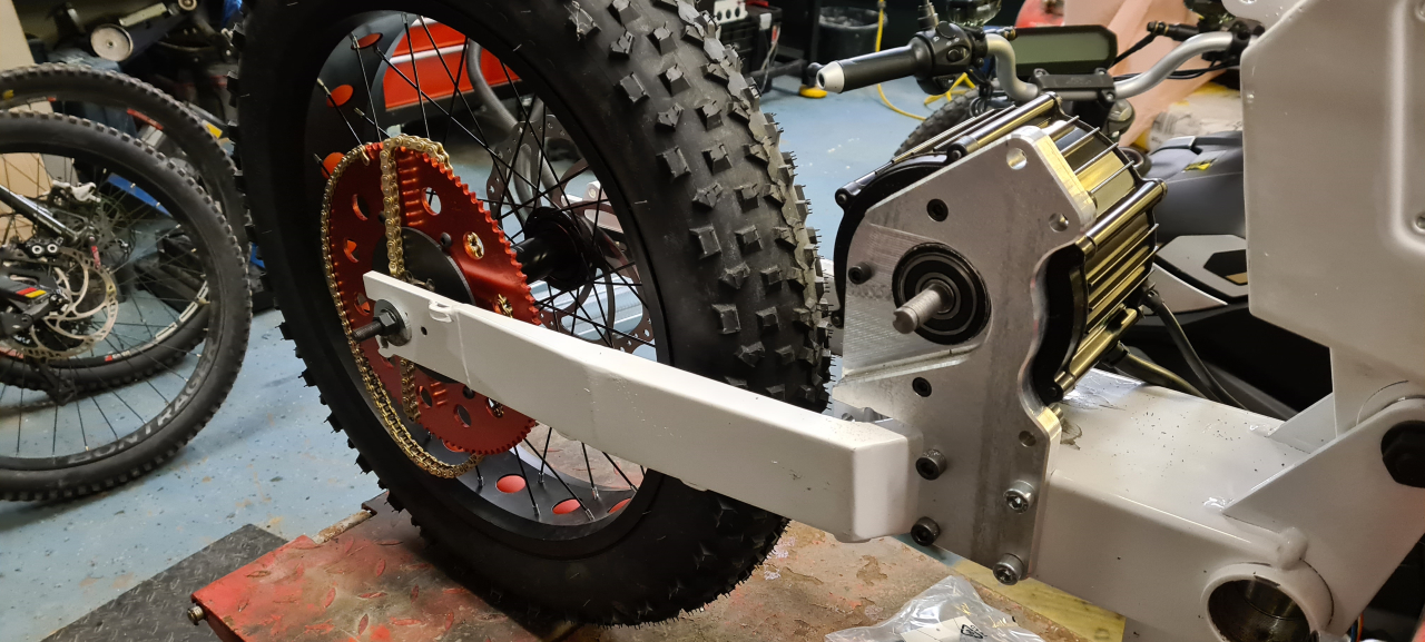
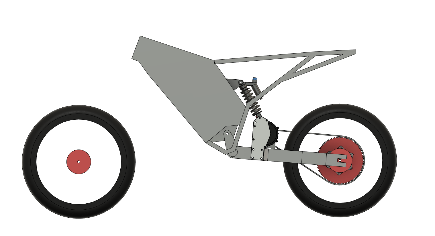
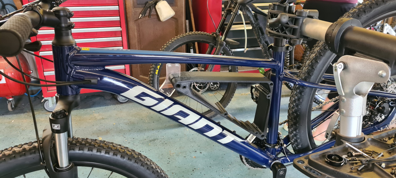
Bolting it down to the frame and mounting the motor everything fits super snugly and I’m starting to question the decision to make a mounting plate on the rear side of the motor too since the motor seems rock solid as it sits now. Buuut, it’s better to make it to tough so we’ll make one just for the fun of it.
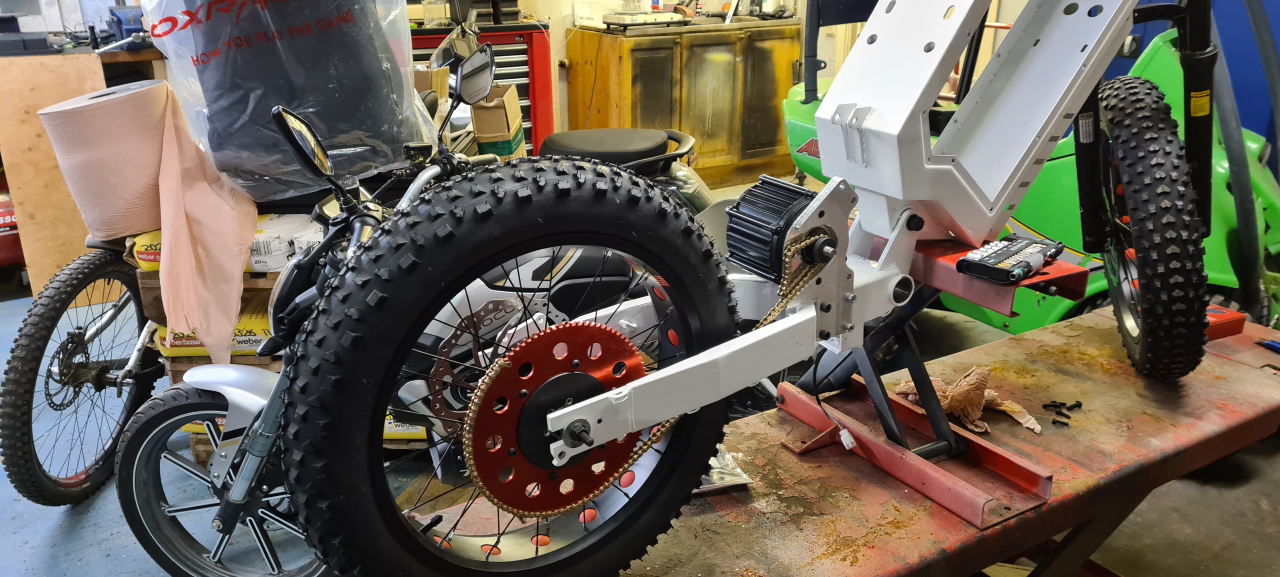
Test fitting the chain again with the proper motor mount. I’ll have to make one last prototype of the rear sprocket adapter but now I get proper clearance to both the wheel and the frame so the next adapter is just to get the chainline straight. Right now I’ve got the largest sprocket I’ll use mounted to make sure the chain doesn’t strike the frame in the worst case scenario.
I’ve been getting parts for the second bike aswell. I’m going to build it up to use as a template for checking the geometry so as not to mess anything up when customizing the bike. It’s a chinese clone frame so the geometry probably isn’t perfect to begin with but it’s good to at least know what I’ve changed when re-designing it.

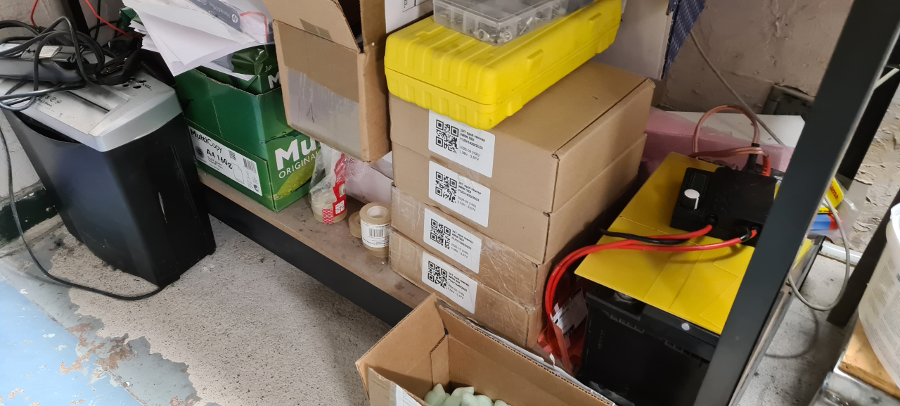
Winter is coming and right now the garage/workshop is a mess with all the projects and stuff that needs storing and protecting from the cold. It’s a bit annoying trying to get stuff done in there but it is what it is. I’ve got to move stuff out when using the plasma cutter that I need for the coming project of making a seat and upper shock mounts..
So, what’s next?
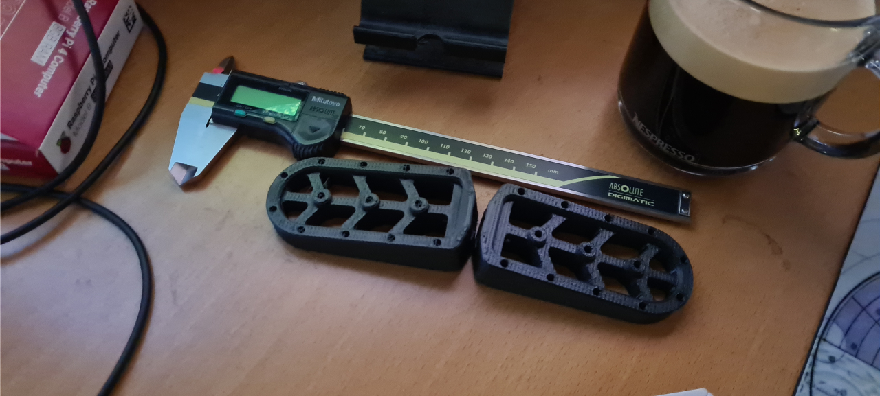
Since footpegs seem utterly expensive I’ve started mocking up custom footpegs for the bikes. I yet have not decided on how and where they should mount to the bike but I know I don’t want them sitting on the swing as the original pedals were mounted on the bomber frame.
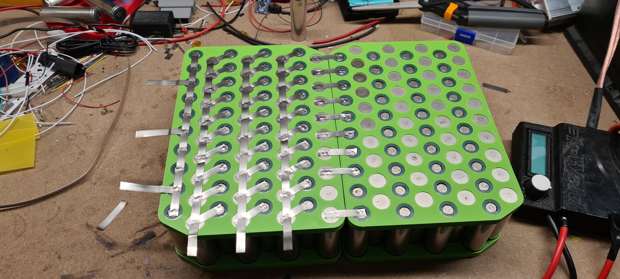
The 21700 cells have arrived so I’m looking at making the batteries for the bikes. It’s going to be a 20s10p pack made from Samsung 30T cells at 3000mAh and 35A.
For the first time ever the build is not restricted by the available space in the frame as the bomber box would fit a HUGE pack if filling it up. I’ve decided to go with 200 cells per pack due to cost and weight. This pack is going to be around 14kg just in cells so it’s going to be heavy enough as it is.
72v nominal at 30Ah yields about 2,2kWh which should let us have fun for at least 100km at a time I hope, of course depending on how we ride. =)
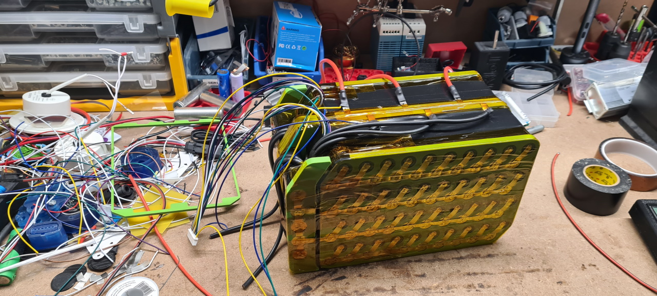
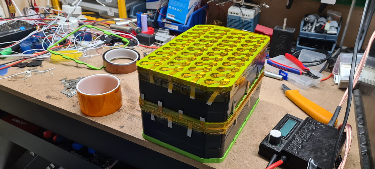
I’m using the same method of building the packs as I do on regular bike packs but as with the avant battery this is going to be a CU sandwich type pack as to be able to deliver 300A of peak current..
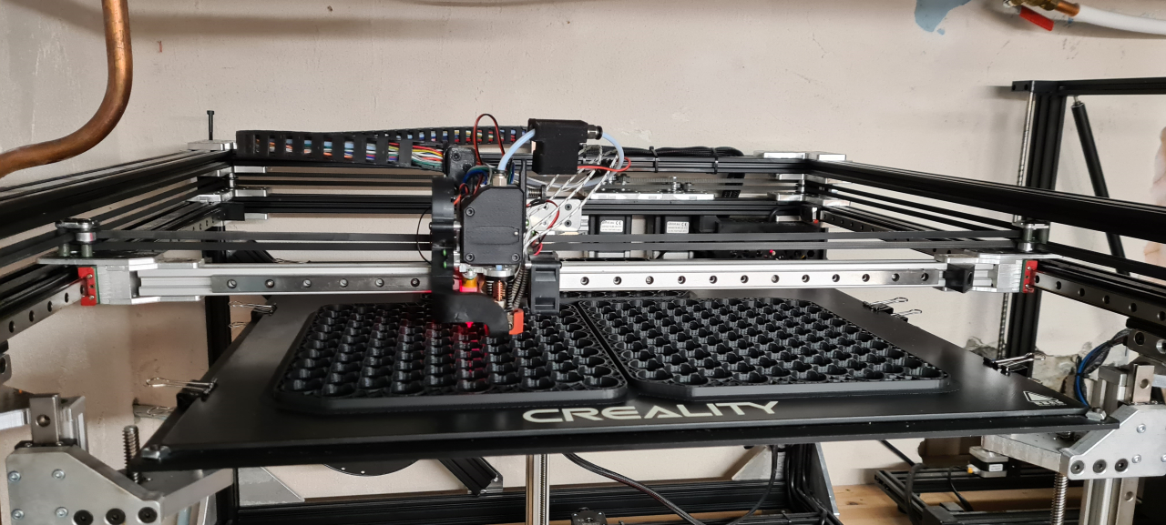
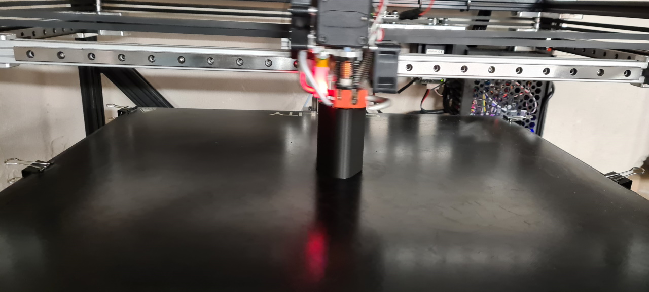
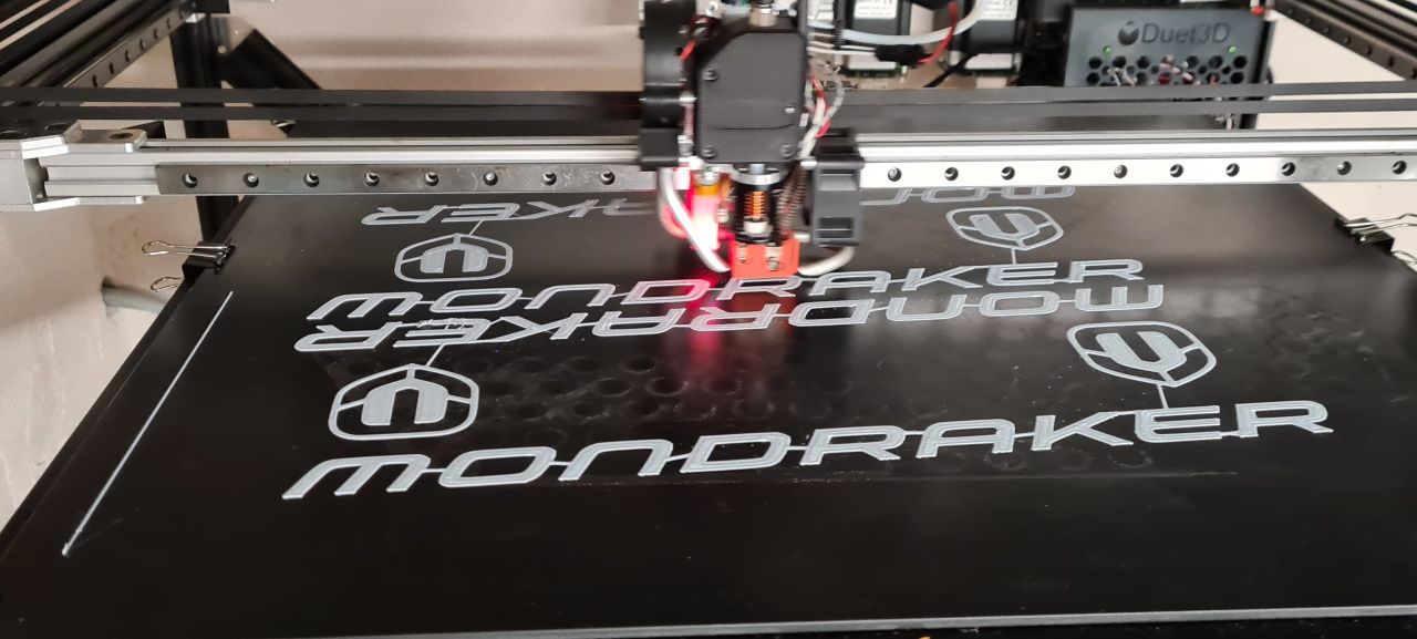
Here I’m printing the cell frames, three at a time, on my ”Stoorn v2”-printer. The next step in the battery process is making cell spacers, measuring the voltage on the cells and starting to put the cells into the pack before welding.
I’ve ordered a pair of ANT 300A BMSes as I’ve used them on all my avant packs and am super happy with the way they work. I’m looking at getting some 10A+ 72v battery chargers to charge the packs in a reasonable amount of time but we’ll see what we end up using.
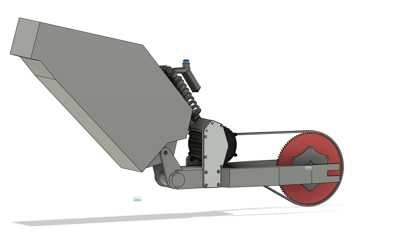
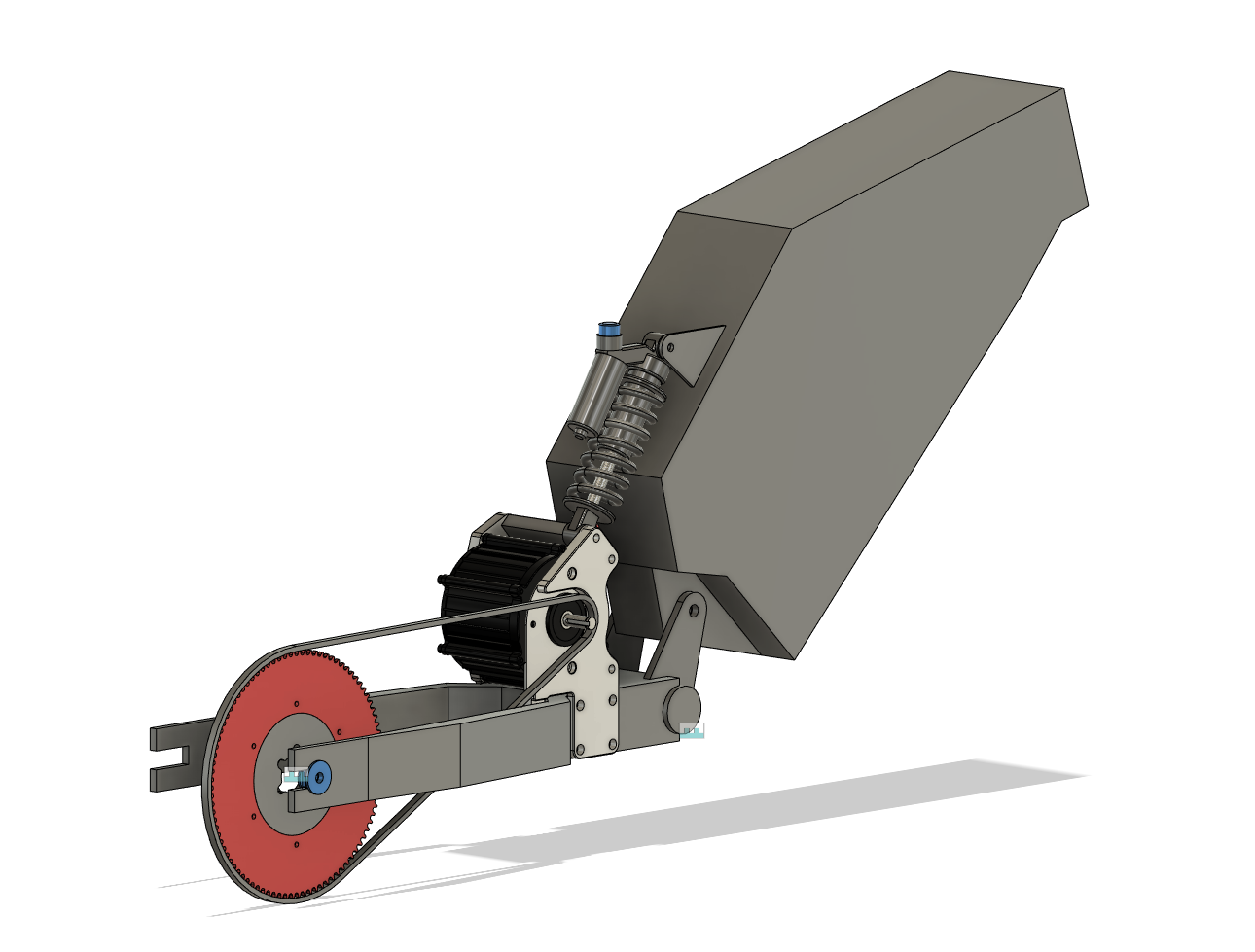
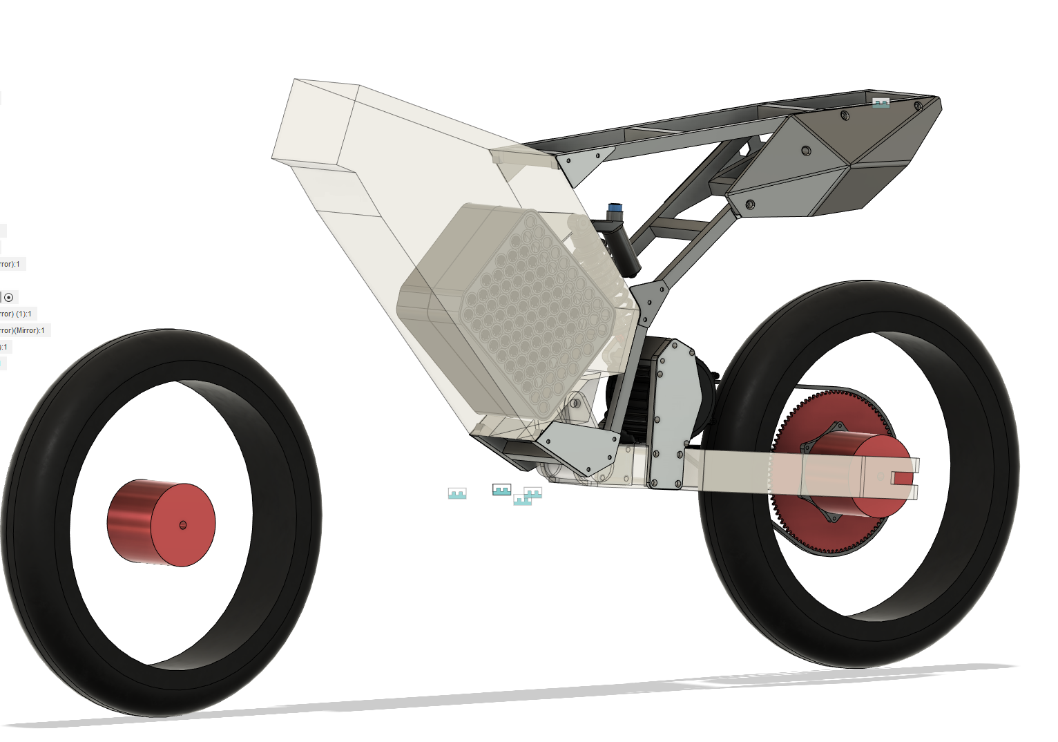
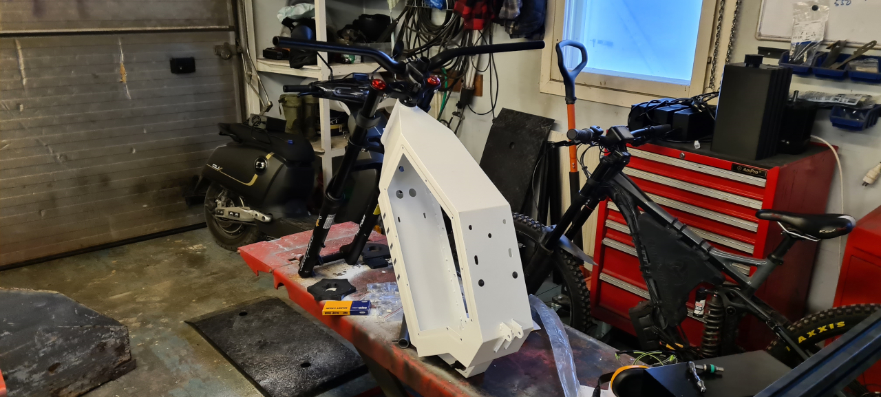
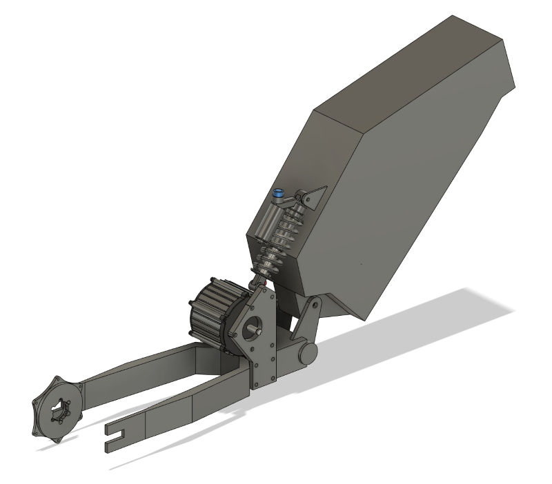
This is where the CAD is currently at. I’ve printed the first iteration of the back plate and am going to fit that on the bike today as I’m milling the adapters for the rear wheel.
I’m trying to make shorter and more frequent updates but as it is now the project stands still for huge amounts of time while I CAD and design and print stuff, and then I’m making progress that shows in a few days.. so I’m doing my best to keep everything updated.
Thanks for reading and if you’ve got questions or comments please post a comment on here or reach out on facebook, instagram or discord.
To be continued..
Having done the mockup for the wheels and mounted the brake rotors and made a mockup for the rear sprocket adapter the next step is mounting the motor.
Since the frame is designed to fit a hub motor and we’re going to use mid-drive motors we need to figure out a good way to mount the motor on the frame. I’ve considered quite a few different positions for the motor but they all have drawbacks. I decided the best solution is to make a motor mount right in front of the rear wheel, making the shortest possible chain line while still keeping the motor as close to the pivot as possible as to limit the unsprung mass momentum of the bike. The tricky part is that this is where the rear shock sits.. So I started by mounting the 200mm shock I’ve got and made the bike sit in the fully extended position on the bench. I then removed the shock, cut the lower shock mounts off and did some measuring.. The CAD turned out like this.
There is going to be a bracket on the left side of the motor too but as of now I’m not sure wether to simply make a motor/shock bracket or to make a new custom endcap for the motor. The right bracket prototype is being printed right now and I’ll use that to check more clearances and get a better feel for the solution. In the CAD I’ve moved the shock all the way to the right to limit the forces on the M8 bolt that holds the shock but where it’s going to go is not yet decided. The upper mount might screw right into the frame or I’ll make it a part of the seat.
I’m going to try to make this modification without welding anything to the frame so it’ll be easier to reproduce if anyone else wants to build a similar ”bike”.
TBC..
Winter is coming and last winter me and the kid agreed on needing fatbikes to ride on the snow..
Of course they’d need powerful motors enough to propel them through the snow and not bog down even when hitting deeper pockets of powder. At first I planned on building my own frames, but as summer came and went and I didn’t have time to get going I decided to get a test frame to start building on to see if our planned setup would pan out..
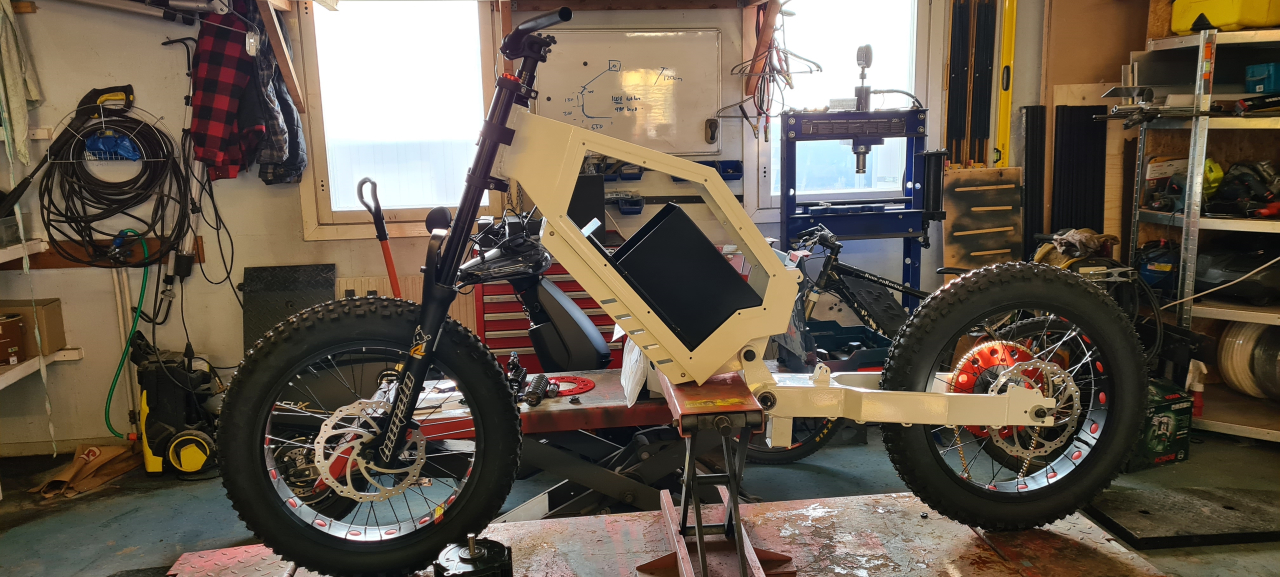
So, this is what I got:
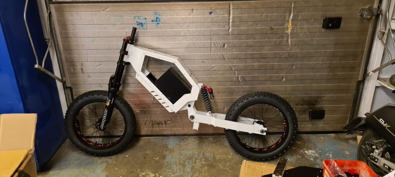
It’s a chinese clone of a ”Stealth bomber” type frame, made entirely from 2mm steel, making it both heavy (20+kg) and sturdy. We’ve got 20″ fatbike wheels on there and personally I think it looks sick. 🙂
The rear suspension I just stole from another bike we’ve previously built and gutted, and the front suspension is a 190mm travel air-sprung fork made 100% from chinesium, but it still seems of rather OK quality.
To get enough power to have fun on these we’re going to use LightningRods BigBlock motors, good for somewhere in the vincinity of 14kW. We’re going to build a couple of hefty 72v battery packs with at least 30Ah capacity and using either ASI BAC2000 or BAC4000 motor controllers to translate the battery DC current to pure joy on the rear wheel.
And yeah, there probably won’t be any reason to put pedals on a bike like this, so we won’t. Footpegs’ll have to do. Since this frame is originally built for hub motors and we’re not using that there are modifications to be made. We’re probably going to fit the motor right where the rear suspension sits right now and move the suspension upwards. A single stage 219 chain reduction will translate the power from the motor shaft to the rear hub. Then we’re building motorcycle style seats to go on the bikes too, some kind of twist throttle, hydraulic brakes, probably have to make my own studded wheels, lights (since it’s mostly dark in the winter) and possibly a kickstand..
Well, that’s the plan. We’ll see how it works out and if we get to ride it this winter. As it sits now the frame, wheels and suspension is in place. I’ve got the motors and controllers but no batteries or other electronics needed. Next week I should get the chain and prockets to be able to start manufacturing adapters to mount stuff where it’s not intended to go and I’ll post updates whenever I get around to it.
First I’ll need to do some modifications to the CNC plasmacutter though to be able to precision cut the parts I need for this project, so that’s next..
So, early this summer season I did something really stupid. I replaced the brake pads on my ebike and took it out for a test.. Riding 50m on the street outside our house being a little bit too tired. The bike was in second gear, I thought it was in third so when I pushed the throttle it wheelied.. a little too much.. Tired as I was I slammed the brakes.. both of them.. so when the front wheel hit the ground it was locked sending me over the bars. Never let go so when the neighbor found me in the ditch I had scratches on the outsides of my hands, my elbow was bleeding badly and I had hit my head pretty bad which knocked me out for a bit. Since I was just going to test the brakes I was not wearing a helmet.. :/
When I regained consciousness I was pretty out of it and after talking to my brother a bit asking the same question over and over he sent me off to the ER. A few stitches, a couple of shots and a complete brain scan later I got to go home with orders to REST.. which of course I did not.
My daughter turned 15 this summer and she got an electric moped for her birthday. Since the bike can fit two batteries I of course had to build one from cells I’ve reclaimed from old scrap ebike batteries..
These are Samsung 30T 3000mAh 21700 cells, good for 35A a piece.
Since the moped and charger says 60V I built this 16s10p pack which would fit the battery compartment in the moped easily.. but then I checked the voltage of the charger and realized it’s a 17s system.. :/ So, I had to put an extra 10s cell on top of the pack making the fit pretty tight, but it still works.
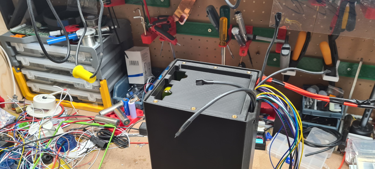
I’ve made the pack in such a way that there’s a SuperSoco connector connected to the 60A BMS and I’ve got 2 XT90 connectors that bypasses the BMS so that I can use the same pack on my future LightningRods BB builds..
The problem is that the SuperSoco uses a serial connection to talk to the battery to display the correct charge state and such which makes this pack show 5% charge even when fully charged.. I’ve ordered a connector that should solve that problem, still waiting to test it.
So.. since I didn’t rest enough after the head injury it kind of never got better. I’ve now been diagnosed with ’fatigue’, when the brain kind of gets overloaded way too easily. This can happen after a serious head trauma I’ve been told, so I need to let the brain rest A LOT for some time to come. This totally sucks. I have not been able to ride my bike this summer as my brain has not been able to keep up with offroad riding..
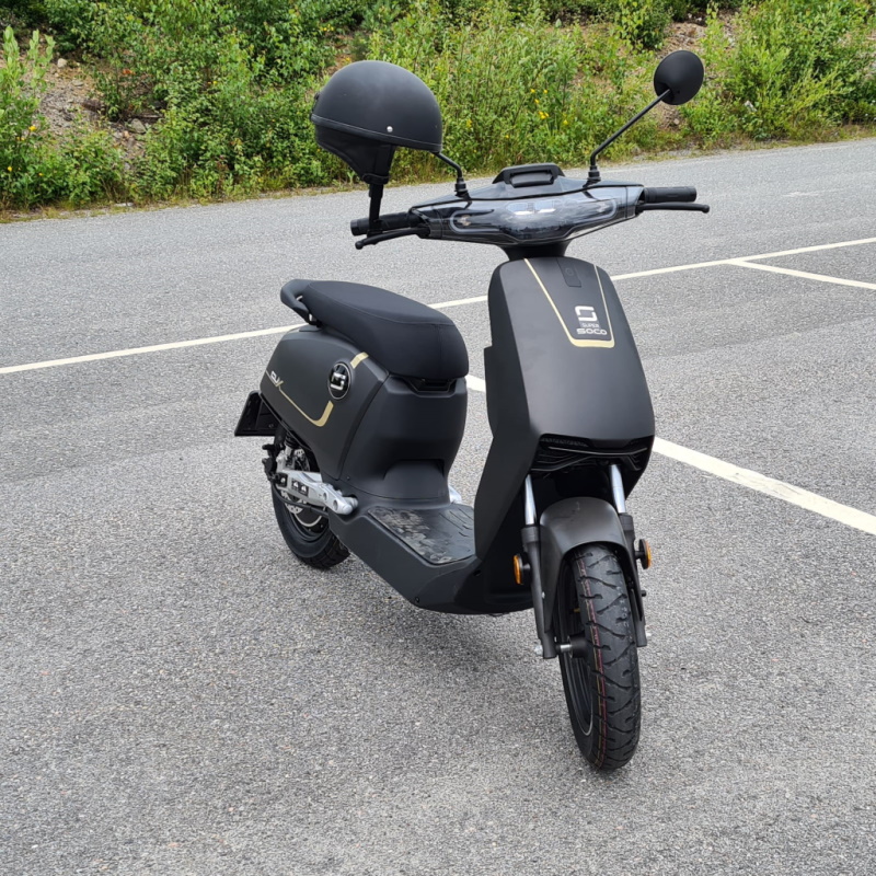
In order to be able to get some 2-wheel action me and my wife got one of these each.. not as quick or agile as the Swoop, but it’s super cozy and quite fun to glide around on!
So, it’s been quite a boring summer due to me not wearing a helmet and having a bit of bad luck.. So, if you’re reading this – take it from me.. wearing a helmet when riding is a super good idea, like EVERY time!
Keep safe – have fun. I’ll soon have more fun projects to share!
Since the only one in the family who didn’t have an electric bike was my wife I of course had to build one for her as well. When asking what the battery should look like the answer was ”It should look like it’s kind of floating in the frame”.. Well..
I had to use the mill for this one, milling 10mm acrylic spacers to hold the edges of the battery pack. Since my beloved wife doesn’t do much offroad racing this’ll be plenty strong enough.
Designed a box shape that follows the frame with an offset. This is a test fit of the outer casing, seems quite ok.
So, after welding a 13s5p pack of LG MJ1 cells the bike turned out quite ok.
The bike is propelled by a BBS02 motor using an eggrider display and performs real good. This motor previously had a problem with the controller where it would say the battery was depleted when it was almost full, but with the eggrider this seems to work just fine.
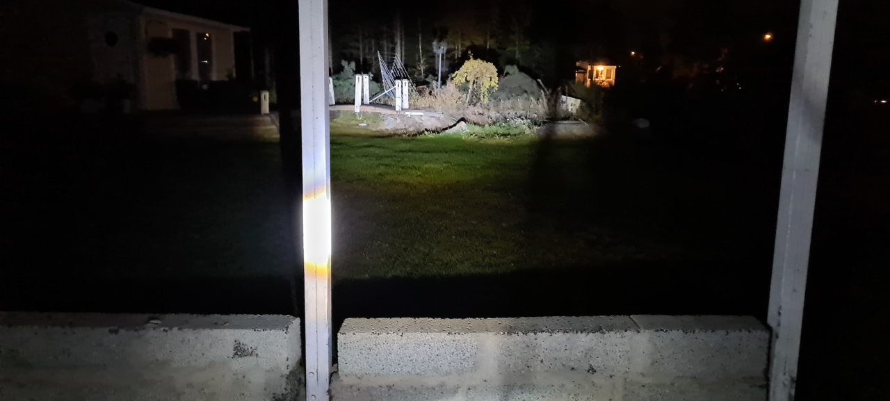
So, autumn is here and with that the total darkness in the evenings.
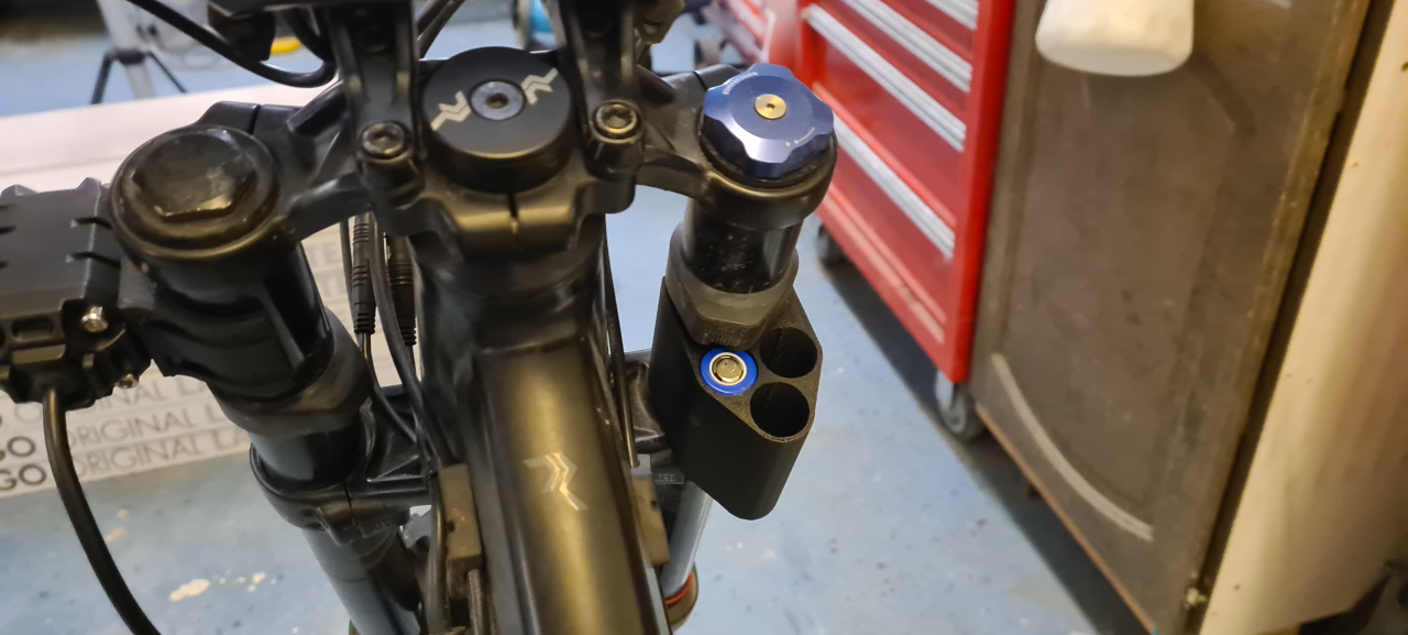
To be able to ride we need a light source that’s easy to mount and remove on the bikes.. so this is the first trial version.
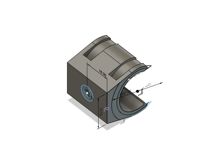
I bought a couple of small LED-lights on amazon and designed a mount that snaps on to the front shocks on my bike..
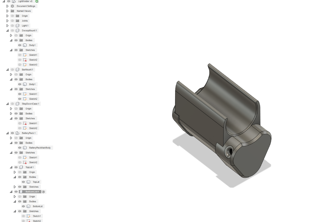
Printed and test fitted it looks something like this.
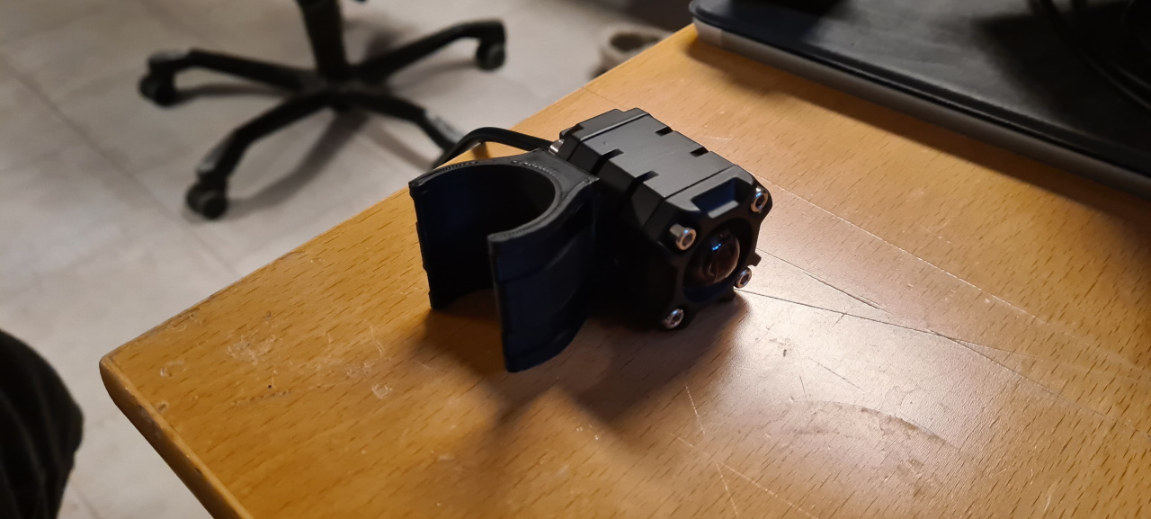
The holder for the light is adjustable both height- and side-wise. It snaps on perfectly and sits pretty snug on the shock..
If testing shows that it self-adjusts I’ll redesign the mount with some TPU inserts to make the mount harder to twist.
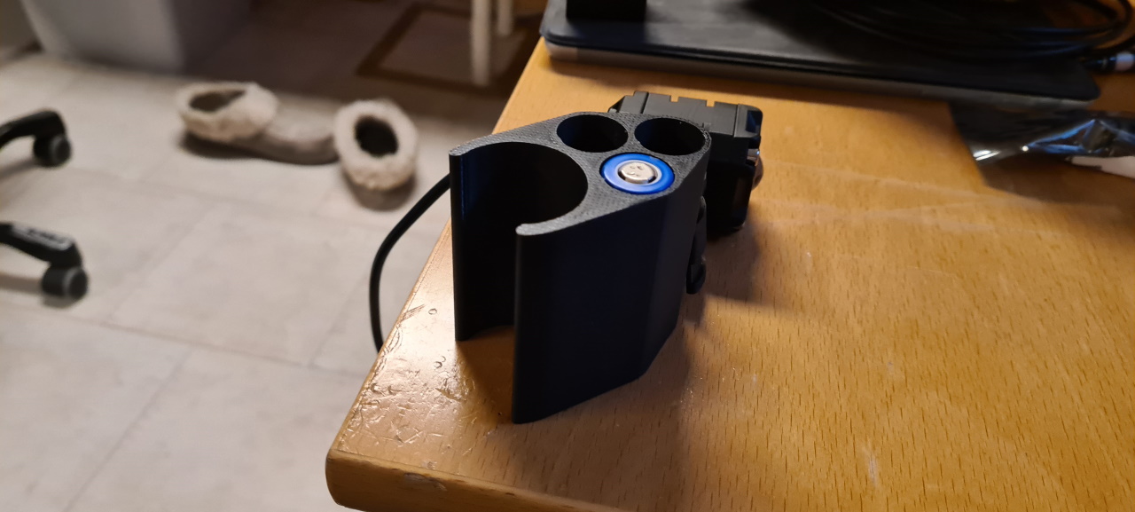
The battery case fits perfectly on the other side..
Welded a battery pack from three 3,5Ah LG MJ1 cells to get a 12V source. I had bought a stepdown that’d work with the main battery but I found no good solution to connect it to the pack so this’ll have to work. For the next bike I’ll be able to connect the stepdown to the charging port so that’ll be what my son will use. My charge port is a bit special so connecting to that can’t be done in any good way that’ll not interfere with my legs when riding..
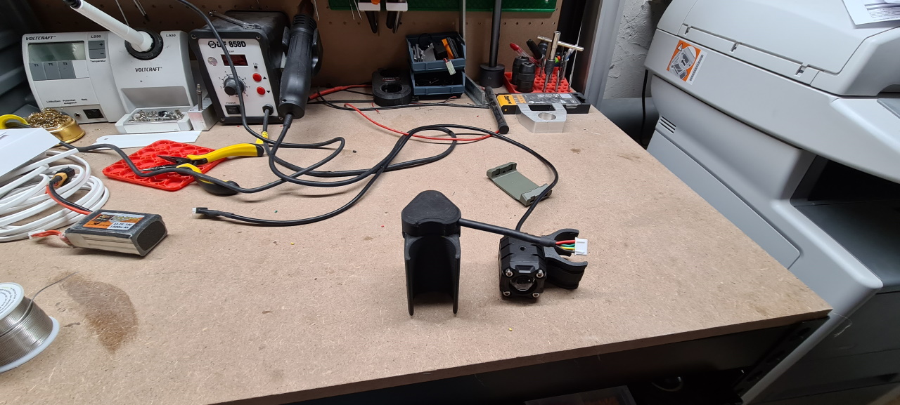
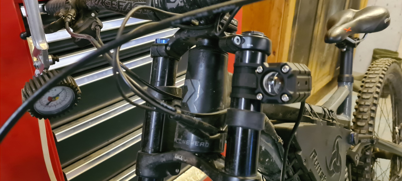
This is the finished kit..
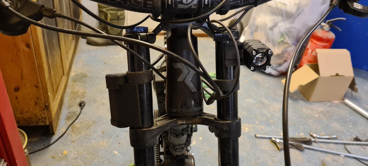
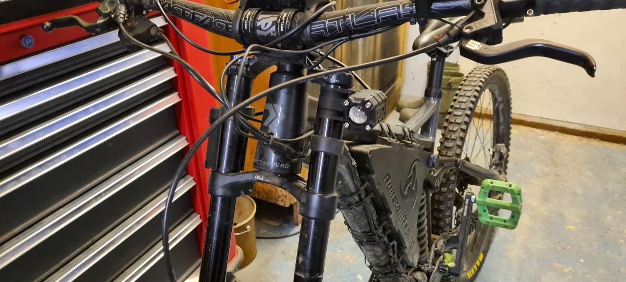
.. mounted on the bike. I had to turn the battery pack outwards a bit to not limit the turning of the handlebars. Next time I’ll put it forward instead which works just as good.
So, the result then?
Well..
The headlight is pretty powerful but it is a bit too narrow. Since it has a – shaped profile of the light it’s also limiting the height of the light which isn’t perfect for riding..
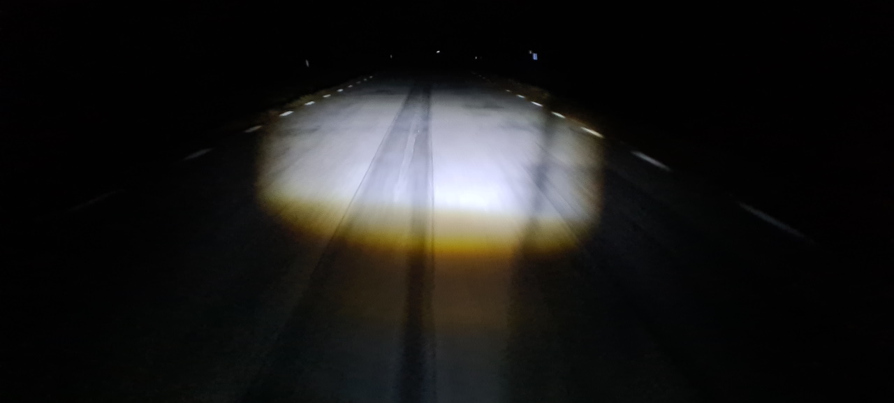
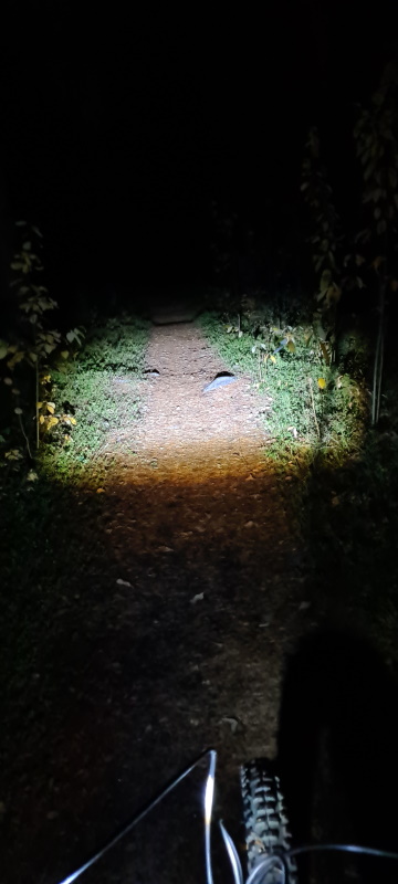
Took a spin on the road and a trip around the local ski track and here the height of the light beam is really hindering. Going 40km/h in the darkness is very tricky with this limited light.. Since I know the track pretty well it’s possible but going around corners means turning into total darkness.
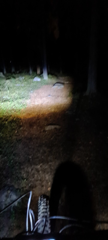
So – conclusion: It works but a wider beam would be better. Will look into modifying this light to cast a wider beam.. The mount however works flawlessly with the light sitting firmly in place and not moving when going over rocky and bumpy sections. So, with a modified or other lamp I think this will be perfect!
Combining this with a helmet light would be perfect so that’s probably what I’ll do. I’ll just have to figure out some good way to mount a battery pack on my neck.. or somewhere close to the helmet. 😉
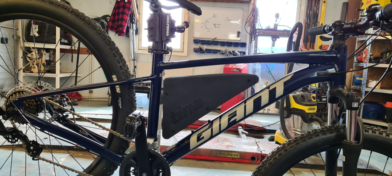
So, after having posted on social media about the boxes I built a finnish friend reached out to me asking for help in printing a box. He already had a design and proper 21700 batteries so I just threw something together in CAD and printed it out for him.
When I asked him for a logo to use he sent me a picture. I don’t know if he was serious or not but this is how it turned out:
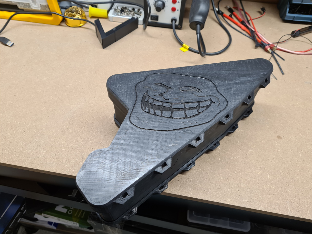
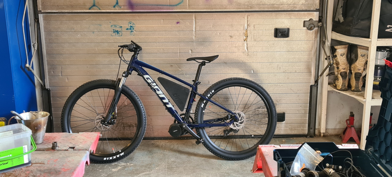
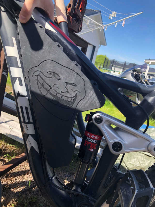
He was happy with the result and the fit in the frame was more or less perfect.
Didn’t get many more pics of this project unfortunately, so this was just a quick update.. there’s still much more to come so stay tuned!
So, a buddy from Italy reached out to me. He had seen what I’d built for myself and my family and had a super nice Mondraker frame for which he could not get a suitable battery case. Since it’s almost impossible to ship batteries abroad I offered to make him a case for him to weld his own pack in.
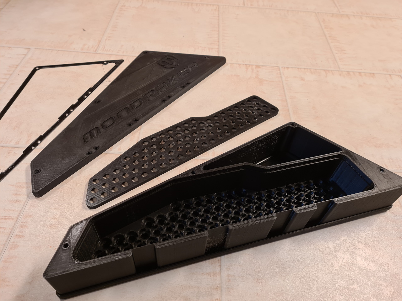
Same method as before but he wanted to fill the entire frame ”triangle” on the bike with the pack, so we made quite the large compartment for the BMS and wiring. This was also done to minimize the total width of the pack and centering it on the frame.
Here you see all the components. The cell frame, the joiner, the sides of the box and the TPU gaskets to make it waterproof(er).
Since my buddy didn’t want visible zipties to mount the pack to the frame we devised a mounting system using CNC milled aluminium brackets to mount to the bottle holder holes and two additional holes he would make.
The brackets are made to make the plastic case survive the forces from the M5 screws holding it to the frame.
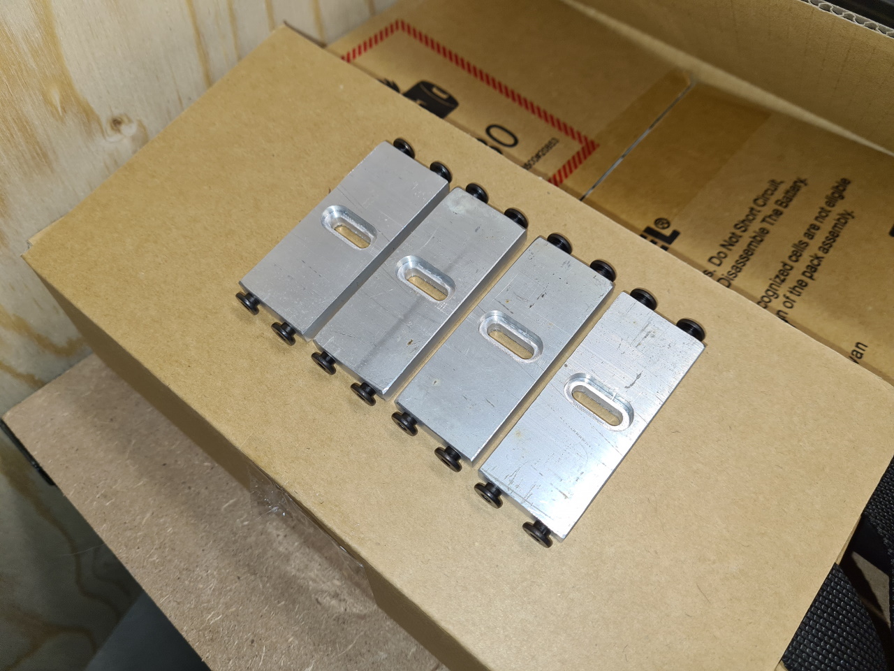
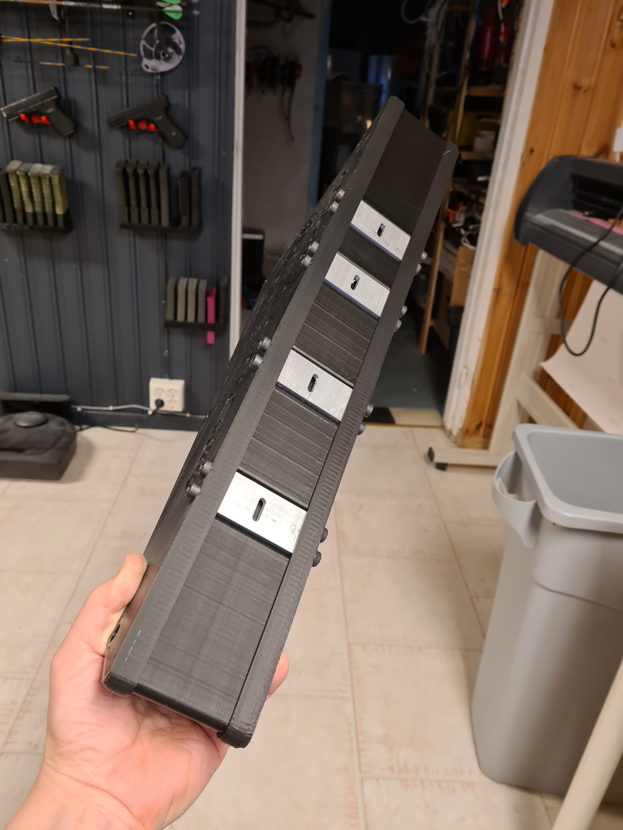
Perfect fit. The bit wierd method of having theese brackets under the box is so we could use the cellframe/joiner method to make it. The brackets are mounted on the frame and the box slid over them before putting the final side on the box. That way the box can be removed without tearing up the cell welds. 😉
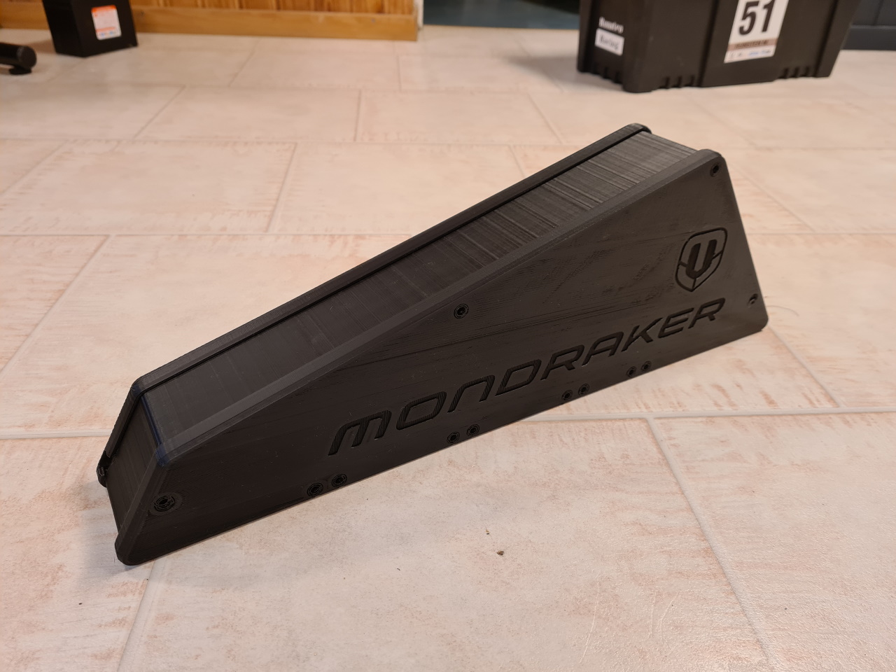
To be able to make the logo more visible I printed white infills.
This box is now in place in Italy enjoying the sun and I got a picture of it all mounted.
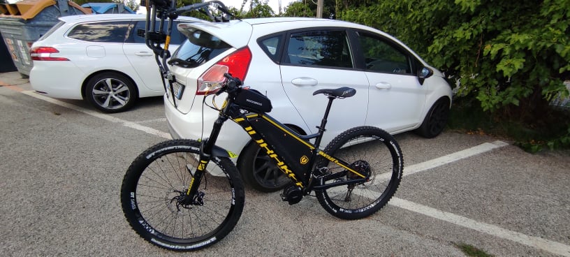
Beautiful bike and the battery fits perfect in the frame!
This was quite an interesting build. The design my pal had already done and he had quite specific requirements for the mounting system and how he wanted it all to look. Turns out he knew what would look awesome in that frame!