CNC plasma CAD files

On popular request I’ve exported the CAD to STEP format for sharing. I’ve done a quick cleanup of the file and all parts named _NOTUSE are not to be used. Most of the custom parts I’ve milled from aluminium but a good 3D print should work just as fine.

If you download and use the file please look at it as a template and feel free to improve wherever it needs improving. My plasma is running with a CUT60 chinese plasma cutter and working fine.

Also, if you build the thing I’d be happy to hear back from you. Please post a comment here or on my youtube channel, https://www.youtube.com/@marcusrunsten and post a link to your build.

All the files and the code for the project is on my github: https://github.com/marcusrunsten/cnc_plasma

Plasma cutting parts for the E-vant

So, at first I finished building the CNC plasma by adding all the electronics and controllers..

I printed a box for the controller and raspberry pi, added all the cables, a relay for the plasma trigger and closed it all off.

I had to do some work with Klipper to get it to work for the plasma cutter. It’s designed for driving 3D printers and making a config that works the way I wanted to was a bit tricky, but as I suspected it was totally possible.

So, after configuring Klipper and writing a custom POST processor for Fusion 360 it was finally time for the first cut..

I placed the CNC plasma on 4040 profiles to get it off the floor, filled a frying pan with water and put a sheet of 1.5mm stainless on the pan.. and off we go!

It actually worked surprisingly well!

Without tweaking it actually cuts pretty cleanly but there is much room for improvement! So, time to put the plasma to work!

I made a shelf for the motor controller for the Evant in CAD, did a quick CAM processing increasing the feed to 2000mm/min and uploaded it to the plasma.

And of course, when I took the video the controller failed. I did some more runs and it seems the X stepper controller has a tendency to reset every now and then.. And then I realised I’m using a 60W 12V PSU.. That means I’ve got a total of 5A to run all the steppers, the controller and the pi.. which was a bit too little. After switching to a 200W PSU everything worked fine!

I made two side walls..

And of course when it’s CNC controlled there’s room for.. well.. flare. 🙂

After tweaking the feed and amps of the plasma I’ve got it to where the cut parts fall off the metal sheet. Sure, there’s room for improvement as I get quite a buildup of steel on the back of the part but a quick runover with the grinder solves that.

I just had to tack weld the parts together to see how well it fits.

It’s not as precise as the mill but MUCH faster, and cuts 3mm steel sheet in seconds!

I’m going to turn the motor 180 degrees to get the cables poking out the back and the controller shelf is going to be turned 90 degrees to mount at the left and front sides of the motor.

Something like this..

We’re getting closer to testing the Evant. Today I got the new belt which I hope will fit the new pulley and motor location.. But this weekend I’m going to focus on building the kitchen so we’ll see how far I get with the Evant. Considering the snowfall here the past week or so it’d be really good to get it running soon..

TBC

Plasma-in-a-week 7/7

Well, since the mechanics were done a while ago what’s left is really just waiting for the new controller board to arrive to start making the electronics for the cutter. I’ve still made some changes to the Z-axis though to make it easier to adjust the belt tension..

These are the bolts that hold the belt on the Z..

This was the intended idler holder where the belt tension was to be adjusted.. But as you can see, and what I didn’t think of, is that the idler obstructs the lower screw making adjusting belt tension hard using this..

So instead I skipped the CNC:ed part and just attached the idler directly to a nut in the extrusion..

After attaching and tensioning the belt all three axis are driven by the belts and stepper motors.. So, if I only had some stepper drivers we could make the cutter move..

TBC

Plasma-in-a-week 6/7

Today has just been about the E-vant build, which is in the next post.. So all I’ve done with the plasma is to assemble the new parts and add a belt to the X axis..

Added the stepper motors to the brackets. I had to make M5 threads in the steppers first.

This is what the complete machine will look like, with some cables and electronics added of course.. and a lot dirtier after the first use.

Just some detailed shots of the nice CNC-work. I really love the look of those CNC:ed aluminium parts with the anodized black extrusions.

Well, tomorrow I’ll finish the build of the mechanical part of the plasma.. So, if nothing unexpected happens it will have taken a week to design, CAD, manufacture and assemble the CNC plasma cutter. 🙂 Yeey.

TBC

Plasma-in-a-week 5/7

So, yesterday was a bit of a bummer when I discovered that the used Cheetah 1.1 controller card I bought from a dude on facebook actually was a dud. No signs of life at all and the uP onboard gets super hot from just applying USB power.. So I went ahead and ordered a new controller for the plasma.. That’s all in the electronics department though and the plan was to get the mechanics finished this week.

So, I needed some spacers for all of the idler pulleys. Didn’t have time to wait for an order so I manufactured these 5.7 and 1.0mm spacers from a spare piece of 6mm aluminium sheet.

After some filing they turned out pretty decent. It’ll have to do for now.

Since I didn’t have enough 2040 profiles I decided to go with some 4040 extrusions for braces instead, so I had to re-mill some brackets to fit.

I made these from 8mm aluminium, not that it’s needed but with M12 bolts it just felt better. =)

So these are all the parts that I made yesterday.. As you can see I made new mounts for the Y stepper motors to accomodate Nema24 motors instead of the Nema17 for which I didn’t have any pulleys.. so, today I’ve got to make some splines in the belt wheel for the E-vant project and then the last of the mechanical parts are going together on the plasma.. We’ll see how it goes.

The black rectangular thing is the 3d-printed electronics box that’s going to house the Raspberry pi and the controller board, more on that later.

TBC

Plasma-in-a-week 4/7

So today I got to breathe unhealthy air at work for 5 hours straight which made me totally beat, so not much progress tonight..

Still I managed to get some work done.

I mounted all the steppers but realised that I don’t have enough pulleys to complete the plasma at home.. Put in an emergency order yesterday for some nuts and belts but totally neglected the pulleys.. So I’ll either have to wait to get proper pulleys or I’ll exchange the Y steppers for some NEMA24 steppers that I have pulleys for.. I’ll decide tomorrow, so we’ll see.. Since I didn’t even have matching NEMA17 steppers for the Y-axis I’ll probably cut new mounts from 6mm aluminium and mount the NEMA24:s.. The Y steppers needs to pull the most weight of them all so..

While not making so much on the mechanical side of things, which is almost finished by the way, I started on the electronics. This is a Raspberry Pi 3b+ that’ll run KlipperOS with Mainsail as a frontend. It’ll push instructions to some old Cheetah1.1 printer controller that I had lying about. It has 4×2209 stepper drivers on it with cooling fins so hopefully that’ll be powerful enough.. Otherwise I’ve got external drivers too.

So the idea is to drive the XYYZ steppers from the 2209:s on the board, use an external relay that’s triggered from the heater output on the board as the trigger signal to the plasma unit and connect the micro switch that’s on the Z axis to the Z endstop on the board. That way I should be able to write scripts that’ll handle all the operations the plasma needs to do..

But that’s for tomorrow.. That and reworking the Y-axis braces and the stepper mounts.

TBC

Plasma-in-a-week 3/7

Back again and tonight has been a good night for the plasma..

After a bunch of hours by the mill this is finally the last part that needs to be spat out before our building can commence.

This small collection of parts seems to be all that’s needed in order to make the XYZ gantry for the CNC plasma cutter.. And when they’re all cut out I just could not resist the urge to do some assembly..

First of all the torch holder goes together with two screws. I’ve cheated and already mounted the linear bearings and the screws to hold them in place.

Then the Z-axis goes together by inserting the 104mm steel rods into the bottom bracket..

.. then the torch holder and lifter is slided onto the steel bars and finally the top bracket is mounted.

A 100mm long 2040 aluminium profile with threaded ends holds the assembly together. I’ll need to go back and add the contraption that is to hold the belt on the lifter but we’ll let that be for now.

The idler pulley holder is added to the assembly..

.. and the Z stepper mount is attached.

After adding the backplate with the V-slot wheels the Z assembly is complete. This is the most complex part of the build, the rest is quite straightforward..

V-slot wheel brackets are added to the ends of the X axis profile. I’m using 1000mm long profiles so the cutter will span 1mx1m and have slightly less work area than that.

The mounting bracket for the X stepper motor is mounted..

.. and the Z assembly is slided on to the X axis. Since the upper v-slot wheel is adjustable with an excentric nut the Z-axis can come off and be remounted any time but for now it was easier to just roll it on there before mounting the X idler holder..

.. which is the last part we need to complete the X axis. I’m not going to use limit switches for homing, I’ll probably just manually zero the X and Y axis where I want the work area to be like I do on the mill..

The Y axis stepper motor mounts are attached to 1000mm long 2040 extrusions..

.. and the opposing idler mounts are attached…

.. and this is the current state. I’ve mounted the Y axis brace holders in the corners of the motion rig but have yet to thread the ends of two more 1000mm extrusions.. Unfortunately I only have one at home so I’ll have to figure something out.. I was pretty sure I had 5pcs at home but it seems I was wrong.

Well, almost all the mechanical parts are together now, tomorrow I’ll start with the electrical stuff to get the cutter to move on its own..

To be continued..

Plasma-in-a-week 2/7

So, today it got late so this’ll just be a quick update – as promised.

Started off after dinner with making the lower and upper brackets for the Z cradle. These go together like this:

To make the rail for the Z carriage with the torch and all.

To drive the Z axis a stepper motor and an idler pully are needed and those need somewhere to go..

.. so I milled all the parts that are 4mm thick in one go. Z stepper motor mount, idler pulley mount, and the mounting brackets for the X axis support beams.

After that I needed a 90x70mm large piece of 10mm aluminium, which I hadn’t.. so I had to go with a 12mm aluminium piece and remove all 2mm of material over the entire part, which was kind of tedious and I probably broke an expensive 8mm single flute endmill.. but..

And that’s all for today. Tomorrow I’ll probably make the rest of the X gantry and start on the Y axis, and hopefully get time to start putting pieces together..

Tbc

CNC-plasma-in-a-week?

So, for quite a while now I’ve had the need for a CNC controlled plasma cutter. I’ve got a manual one but I’m just not enough of an artist to make good, clean and precise cuts with it.. at least not in sheet metal thicker than a millimeter or two.. So, now that I needed some semi-precise-cut steel sheet for the battery boxes on the E-vant I decided to build the plasma I’ve never got around to building.

But..

I really don’t have the time to fiddle with a DIY build at the moment with the kitchen arriving this week and a surgery for a cyst in my jaw coming up next week so – this’ll be a rush build. I challenged myself to build the entire mechanics for the plasma in one week – this week.. so here goes. I’ll try to update the blog every night..

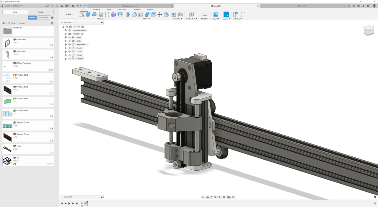
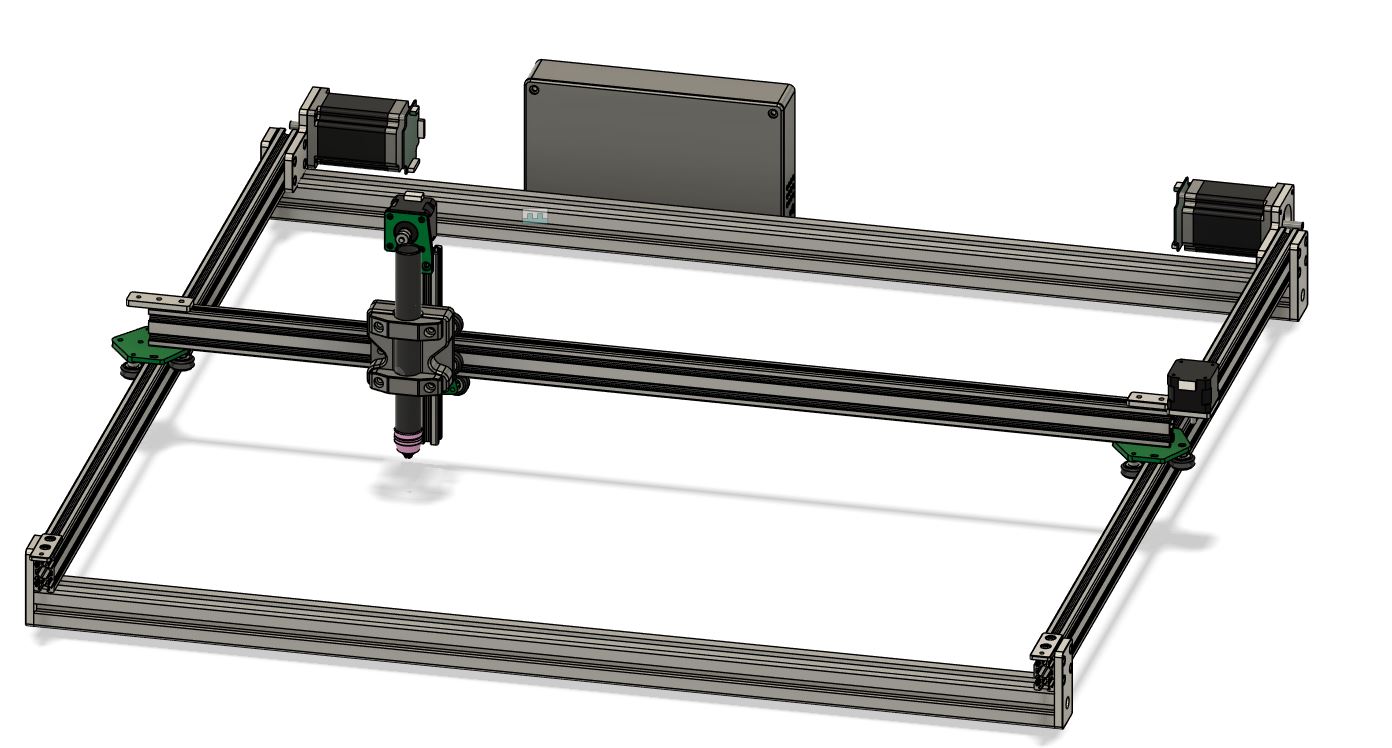
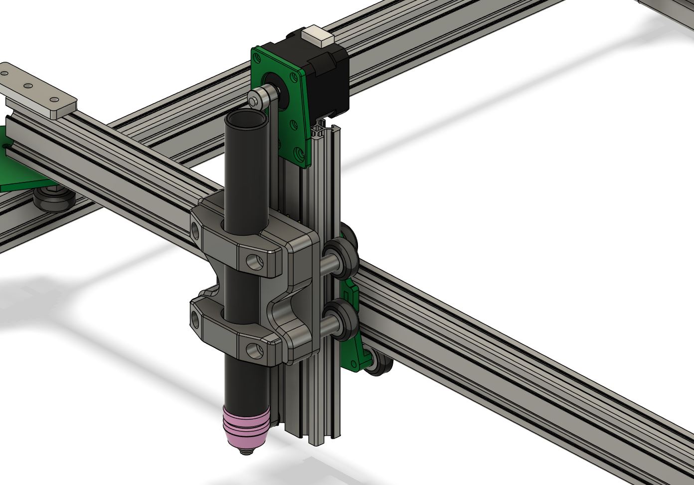
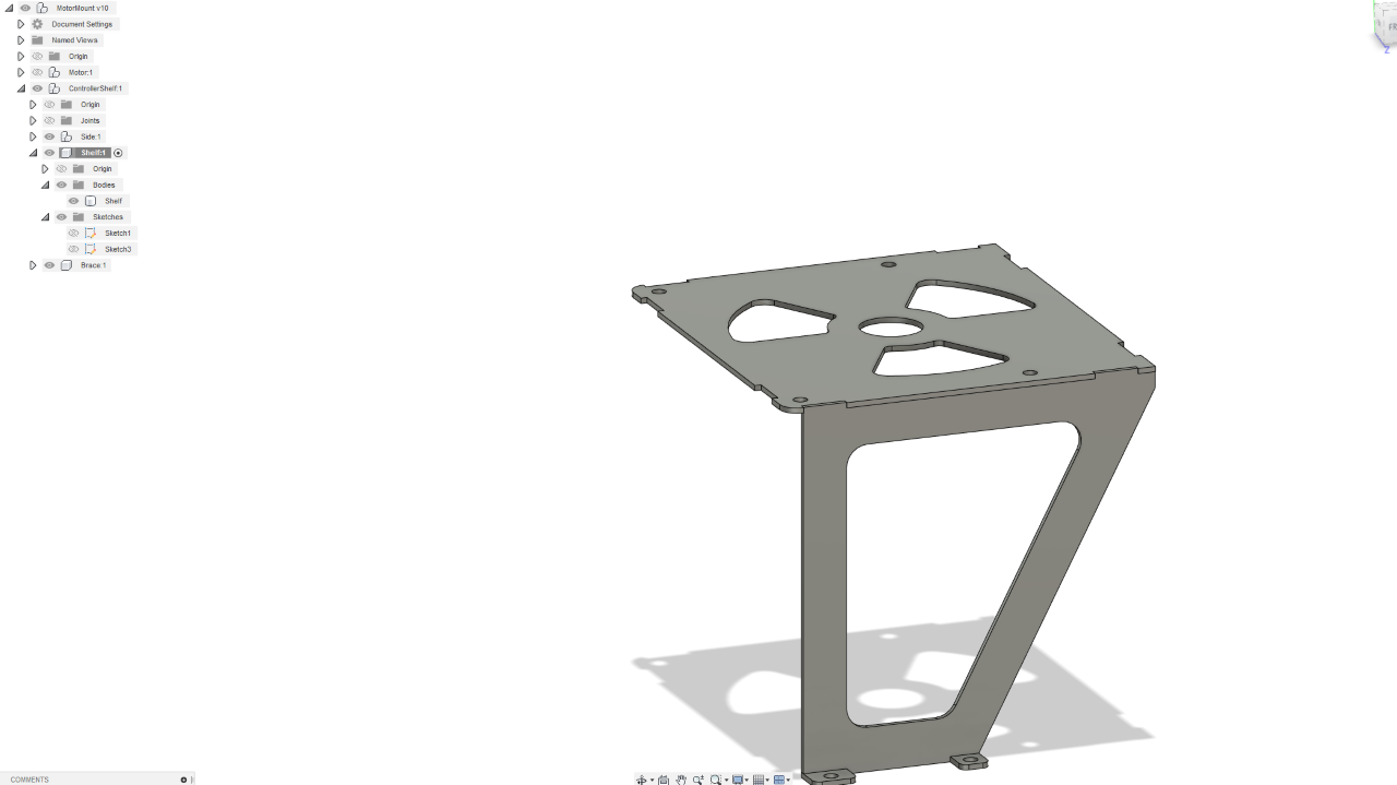
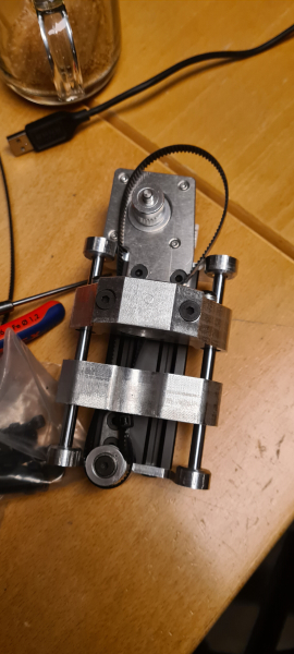
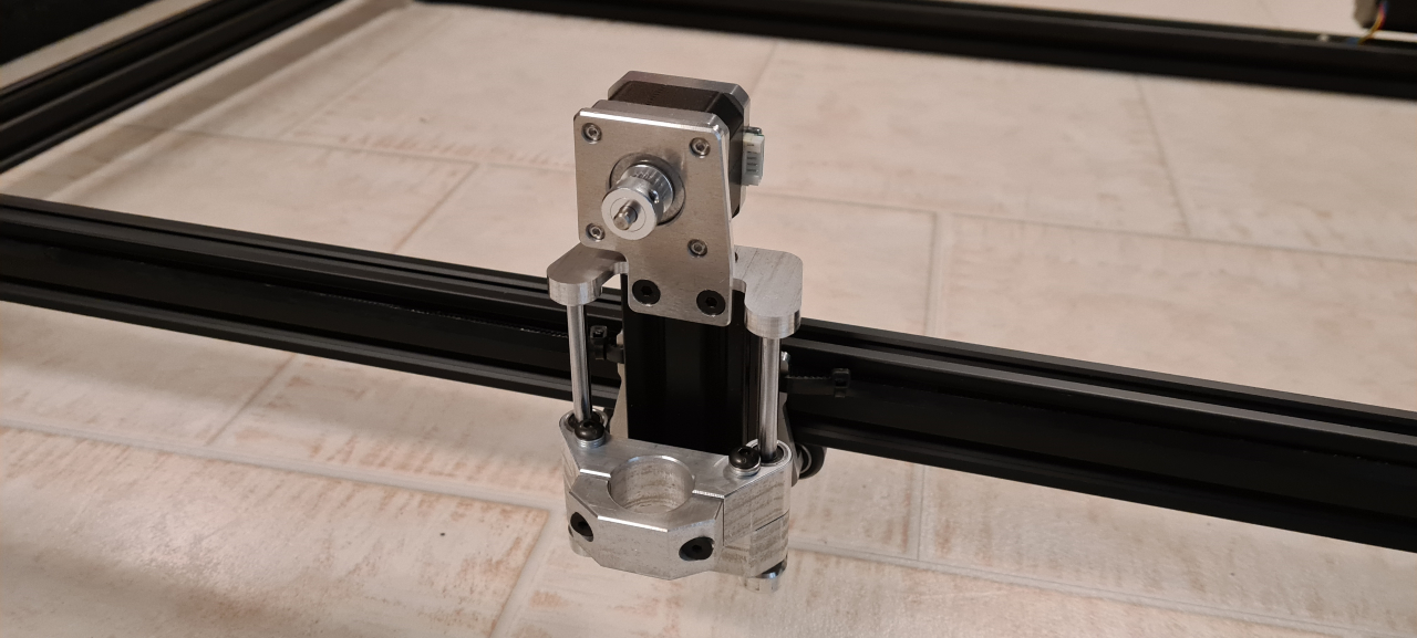
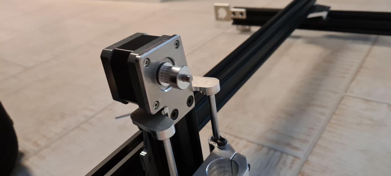
So, today – monday – being the first day of the project I started off doing some CAD. First of all the plasma head holder with the Z axis. This’ll have one cradle holding the torch and another cradle underneath connected to the Z stepper motor. This way I can make the cutter sense the height of the metal sheet and do the scrape ignition of the plasma.. Yeah, I didn’t get the HF-start on the plasma cutter so.. this’ll have to do.

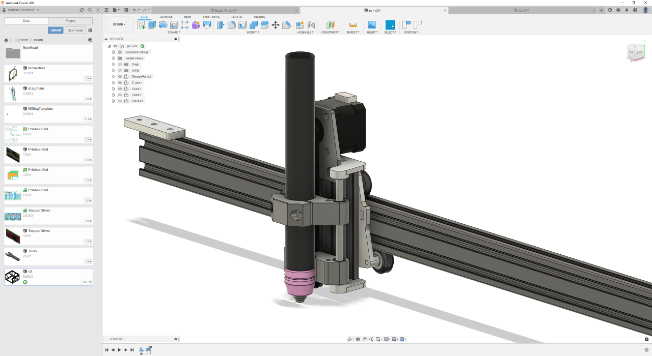
I did however, long ago, get one of those tube-shaped plasma torches so that’s what we’ll use for the CNC..

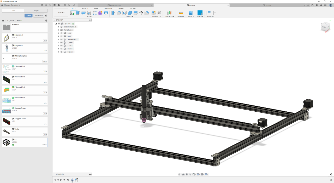
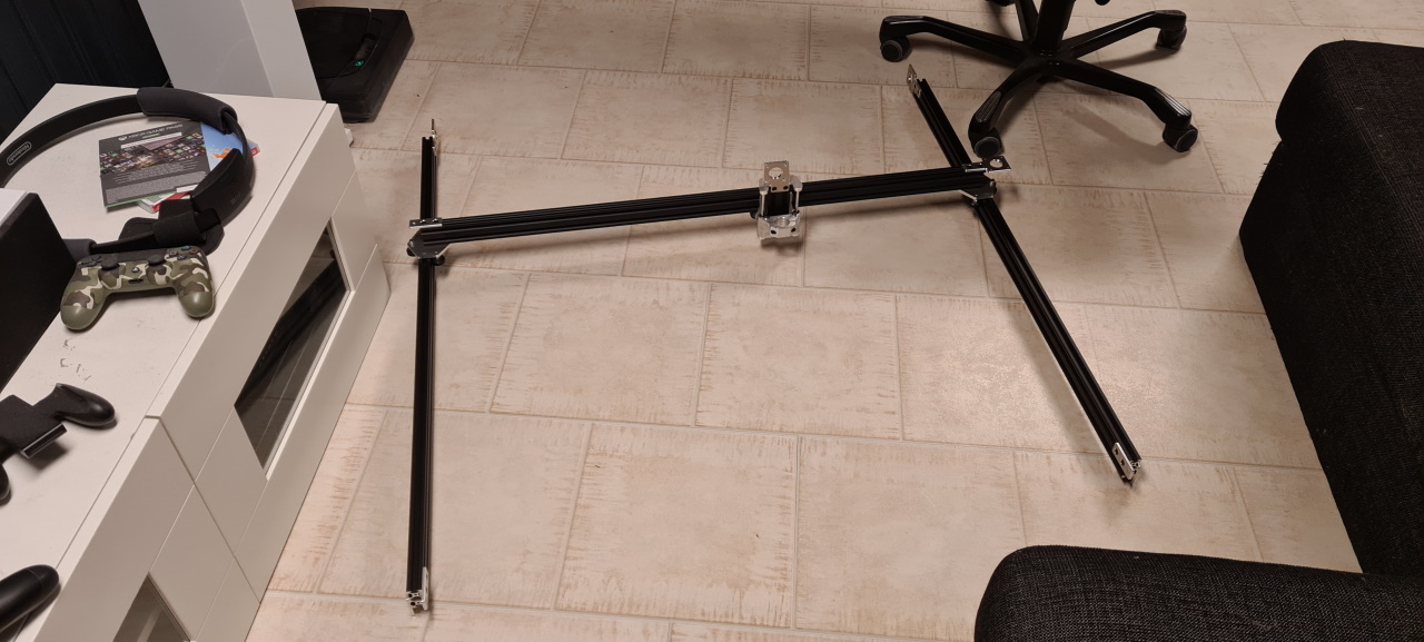
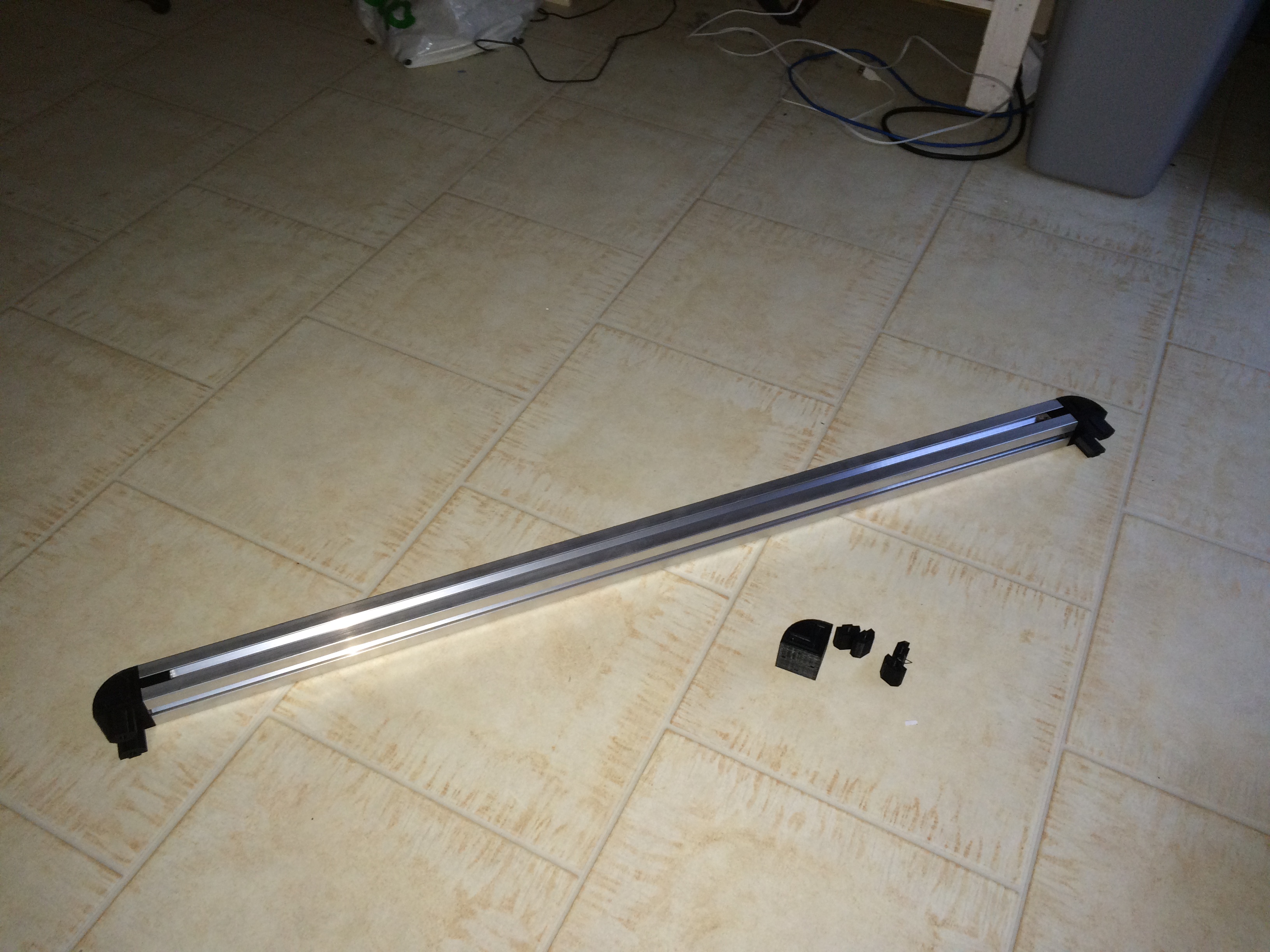
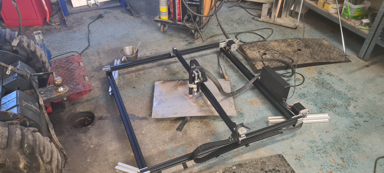
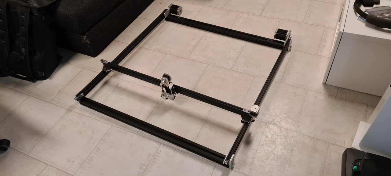
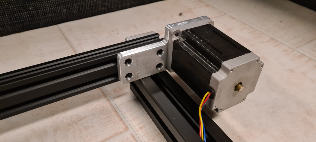
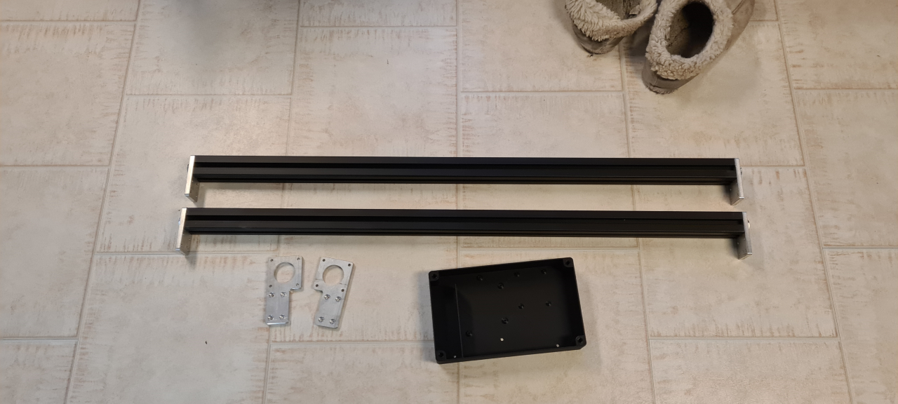
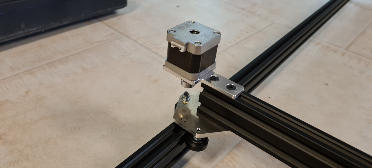
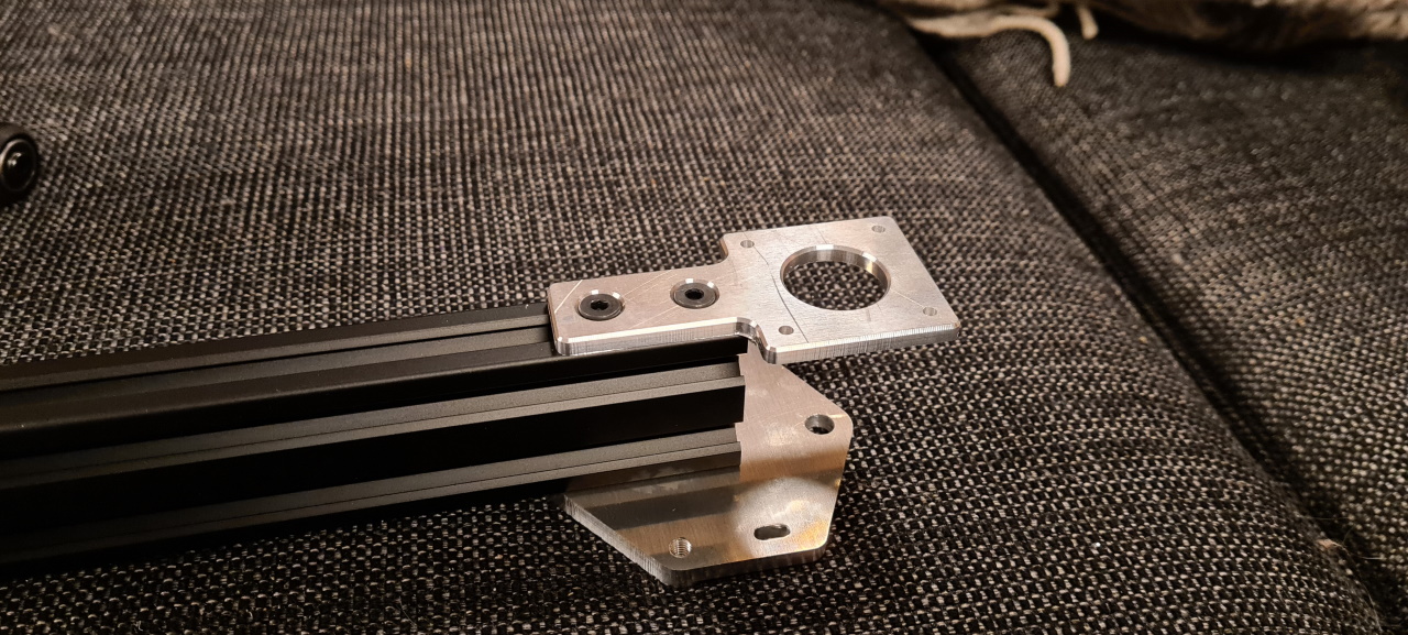
Making the X and Y gantry and the support frame was a pretty quick job and then.. CAM.

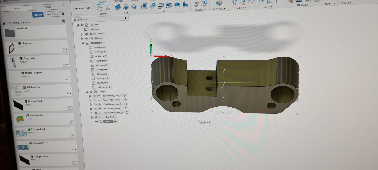
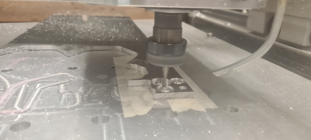
To get the CNC mill to spit out the parts from the raw aluminium blocks you have to prepare the gcode files using a CAM processor. This is where you set up each and every operation the mill has to perform in order to cut the right part the right way. It’s a bit finnicky but after having done this for some time you learn.. I’ve broken many cutters in the process but today I didn’t break a single one.

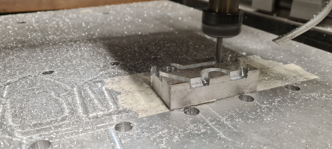
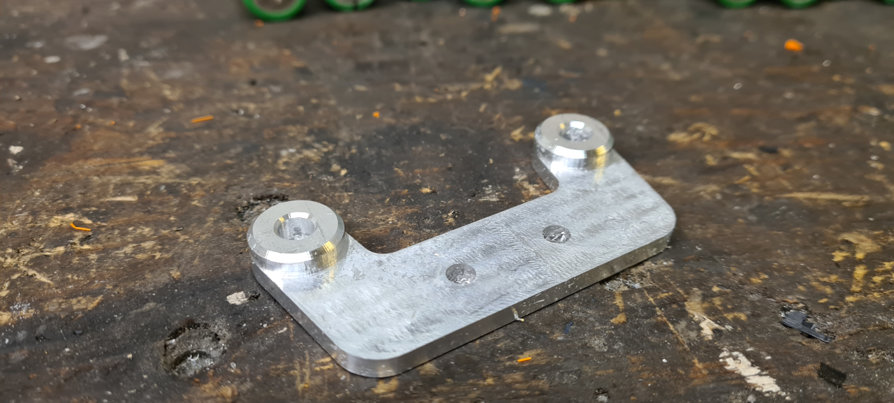
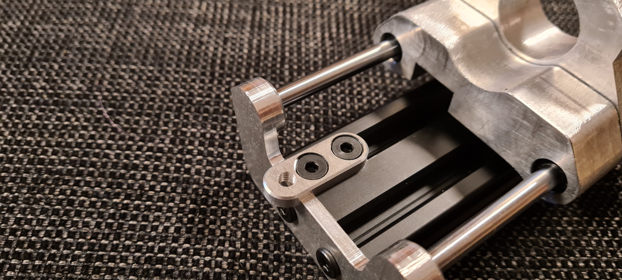
I started off making the most complicated parts. This part, the torch holder, needs to be processed from three different angles. Since I only have a 3 axis CNC-mill I have to mill the first side, then remove the part from the mill, re-fasten it in the next orientation, do all the work from that angle and then do the repositioning all over again. For each time the part is loosened I have to re-zero the X-, Y-, and Z-axis.. which takes some time.. but.. well..

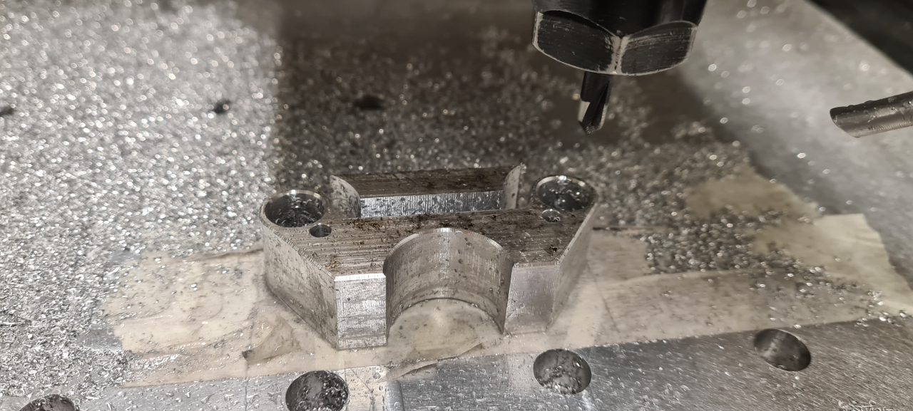
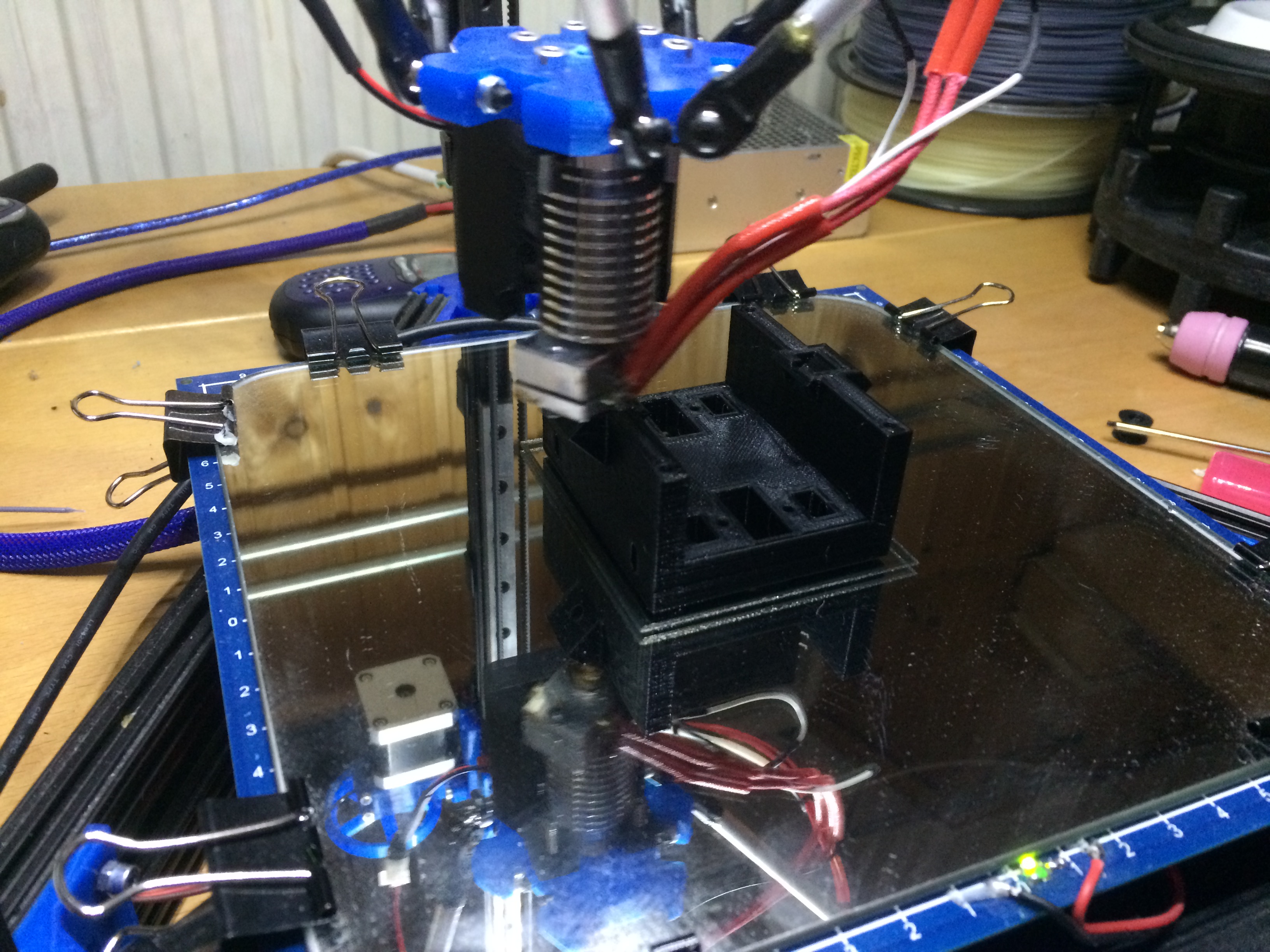
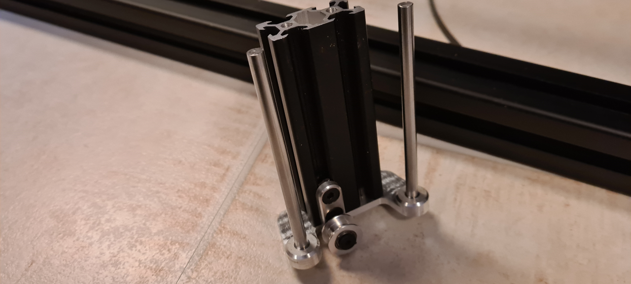
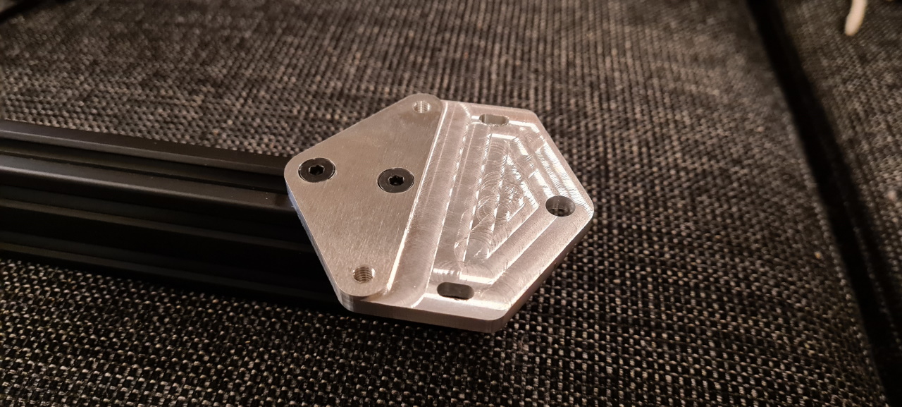
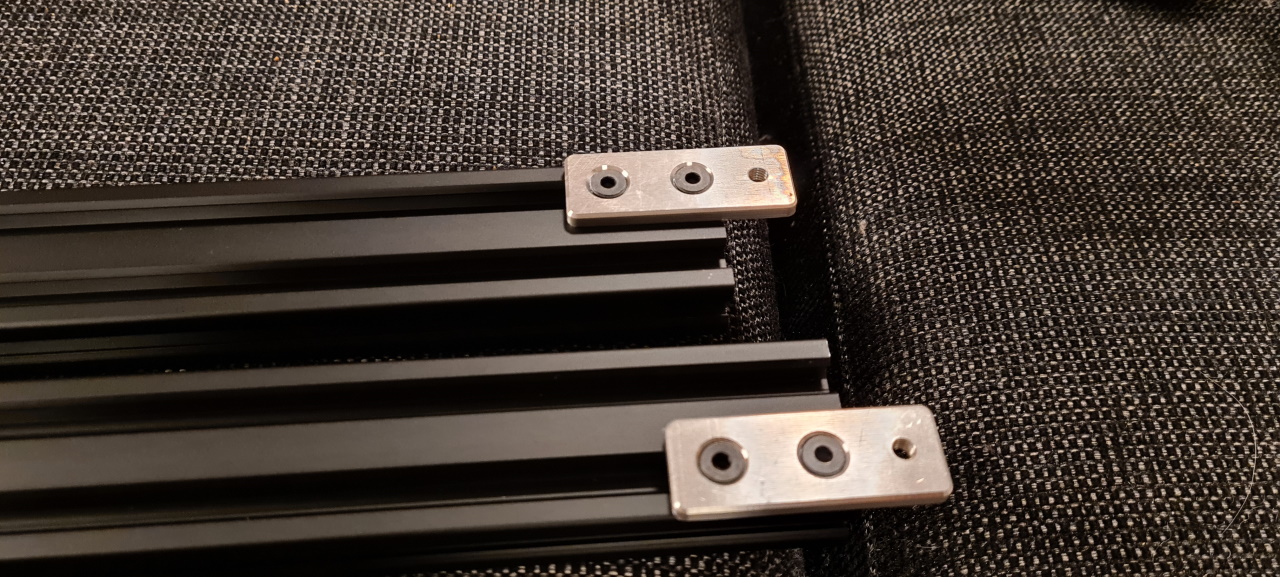
When the mill is done with the first orientation and after a quick chamfer of the part, this is what it looks like..

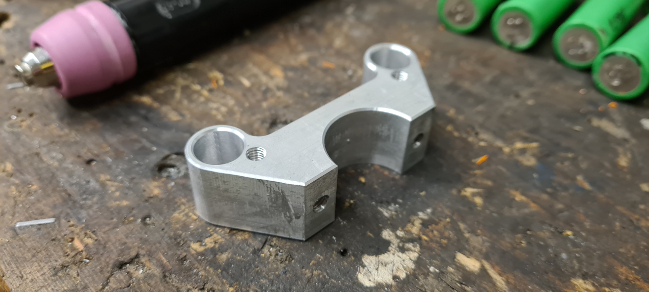
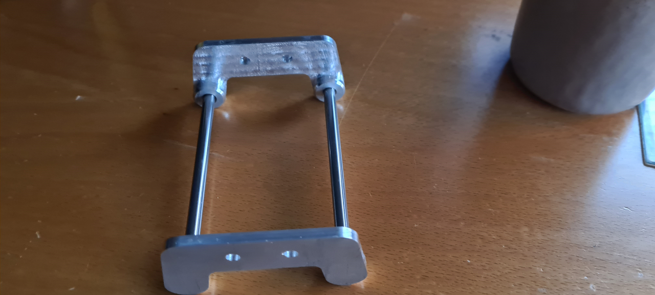
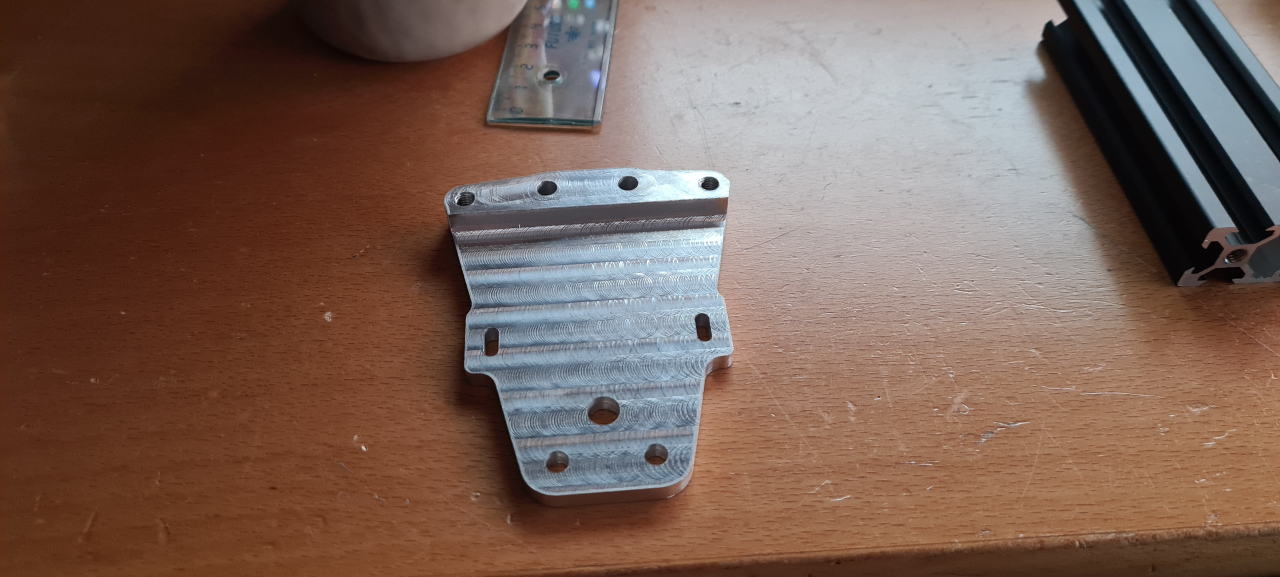
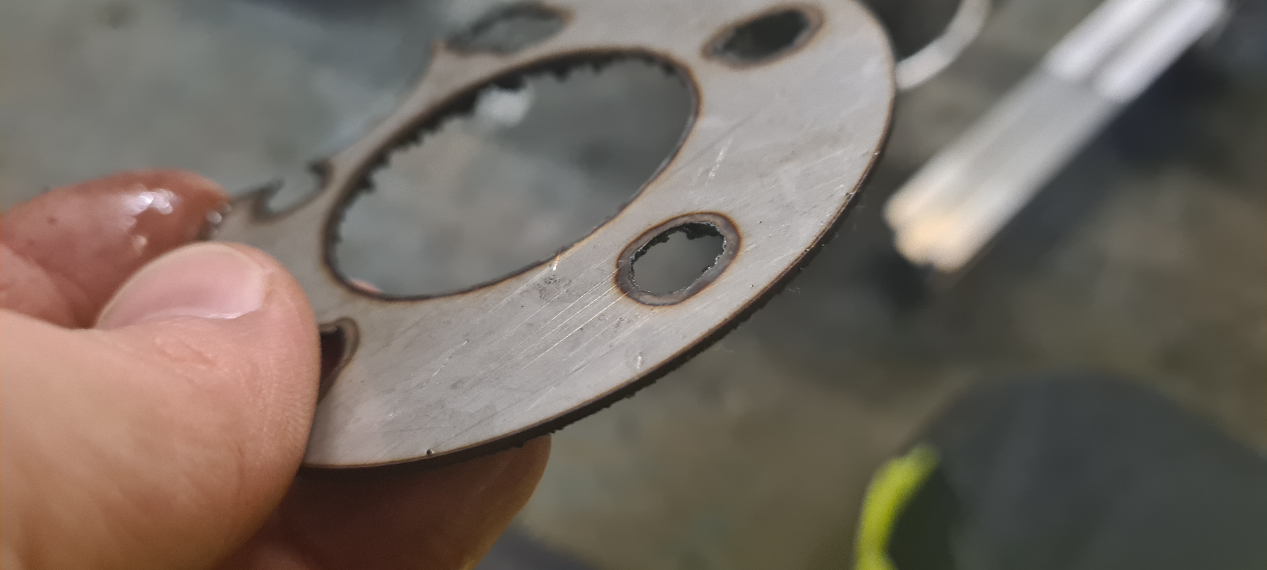
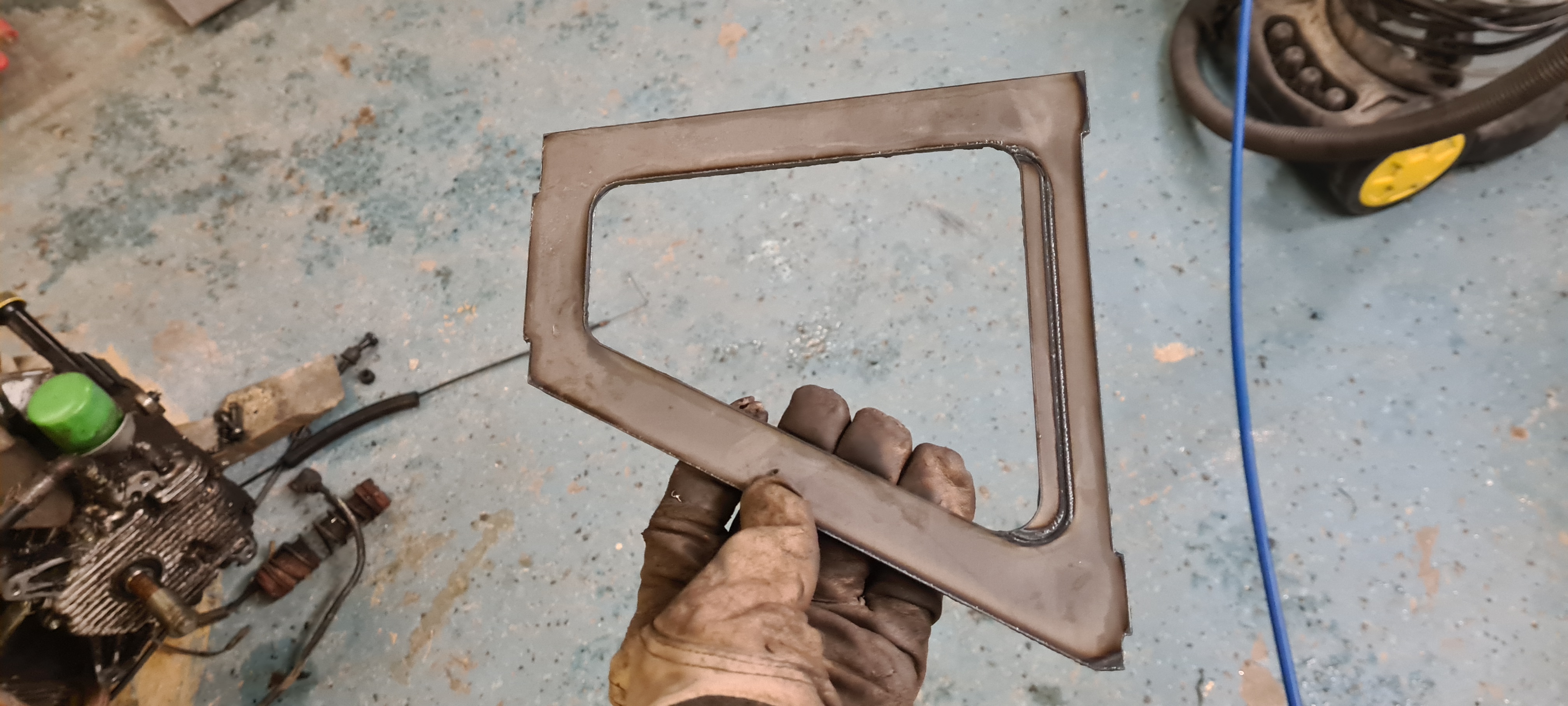
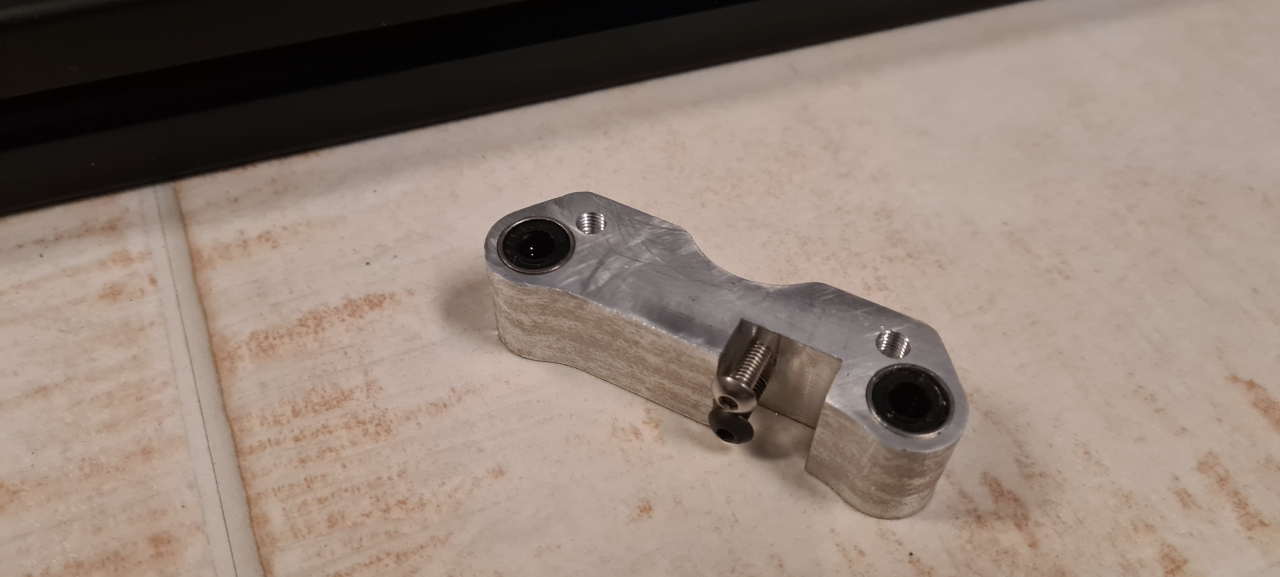
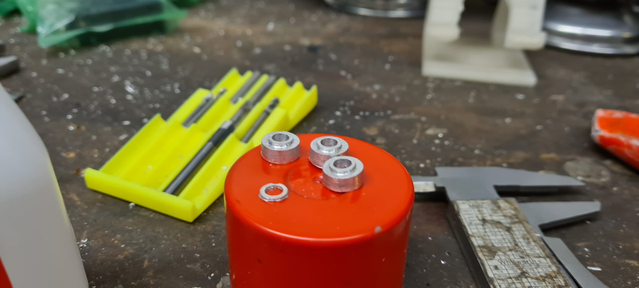
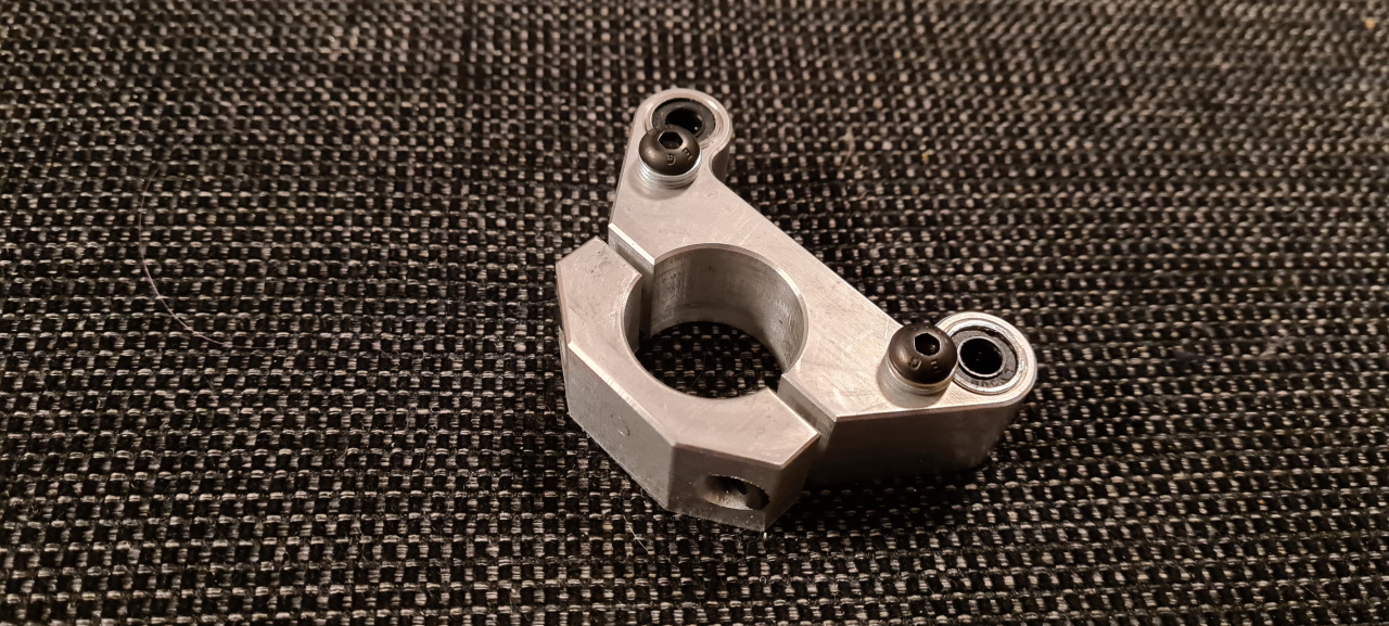
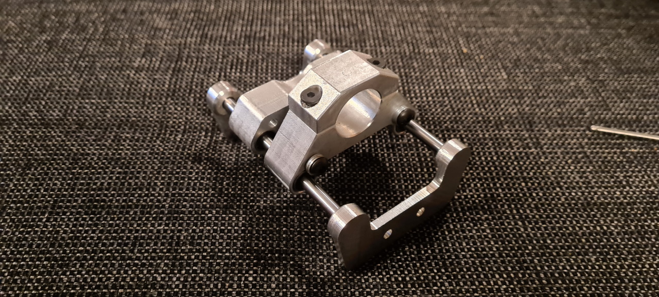
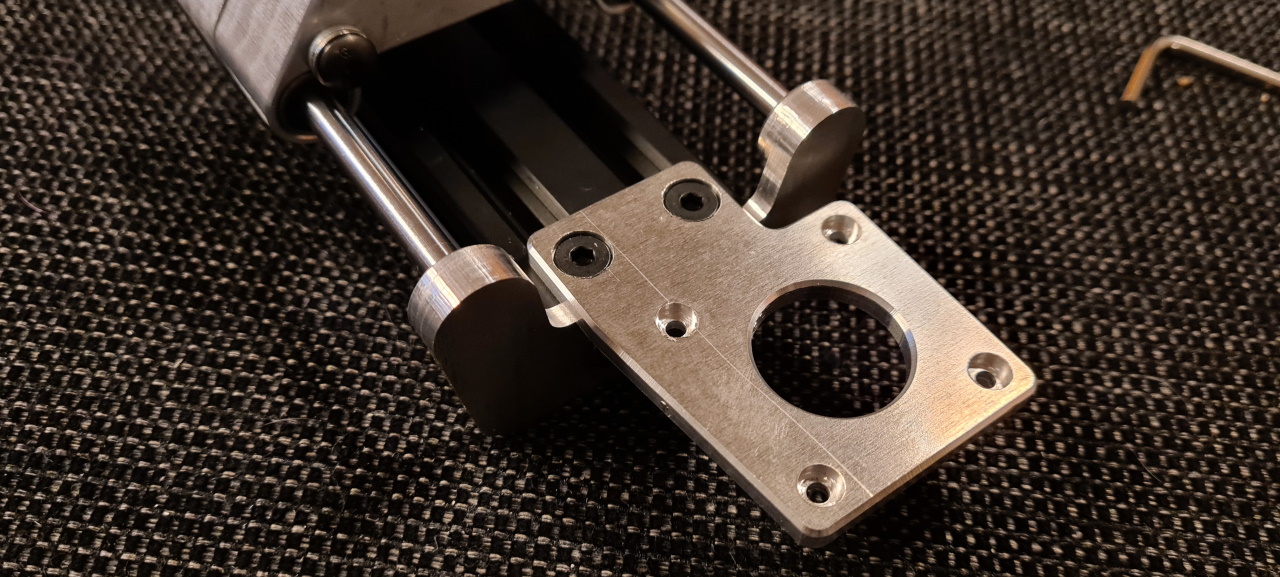
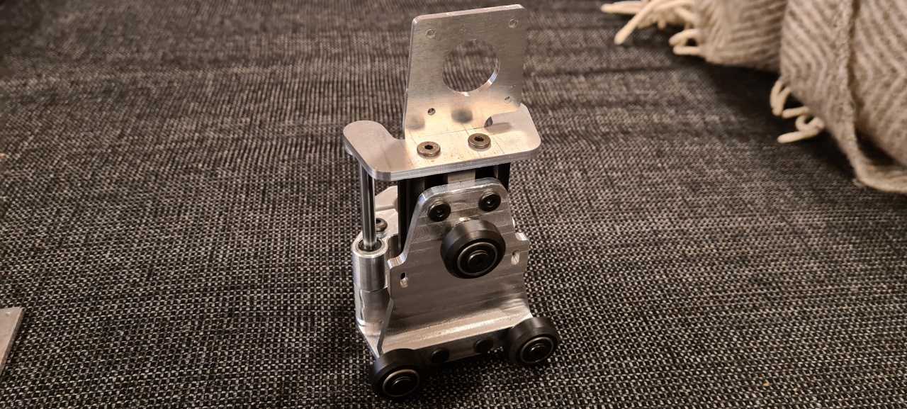
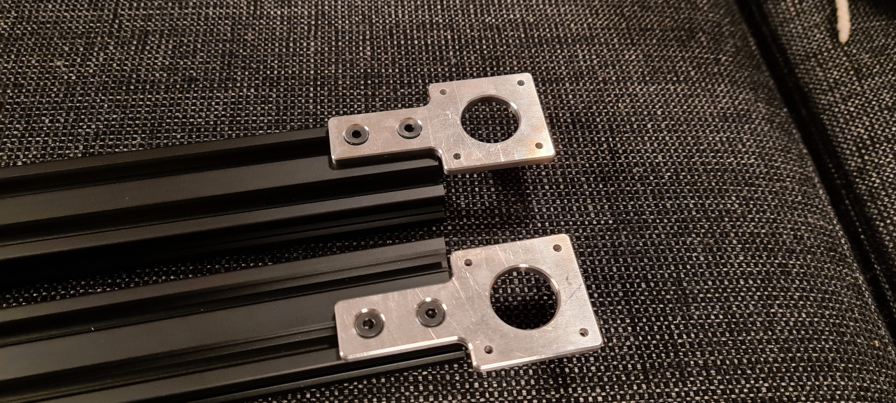
.. and this is the same part after doing all the operations and cleaning it up a little.

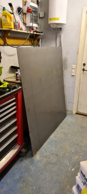
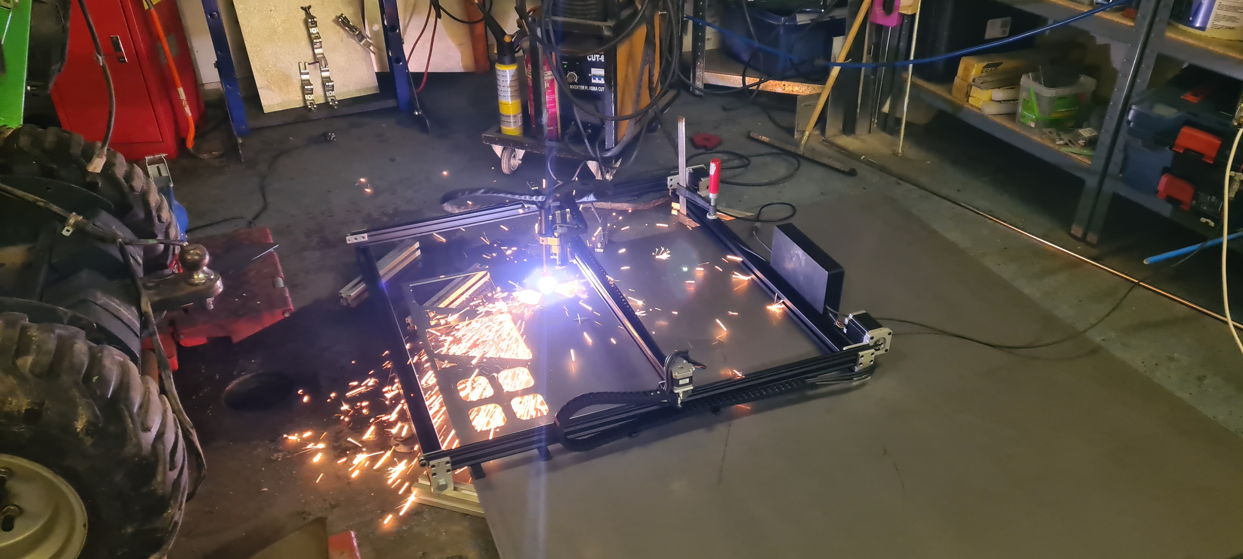
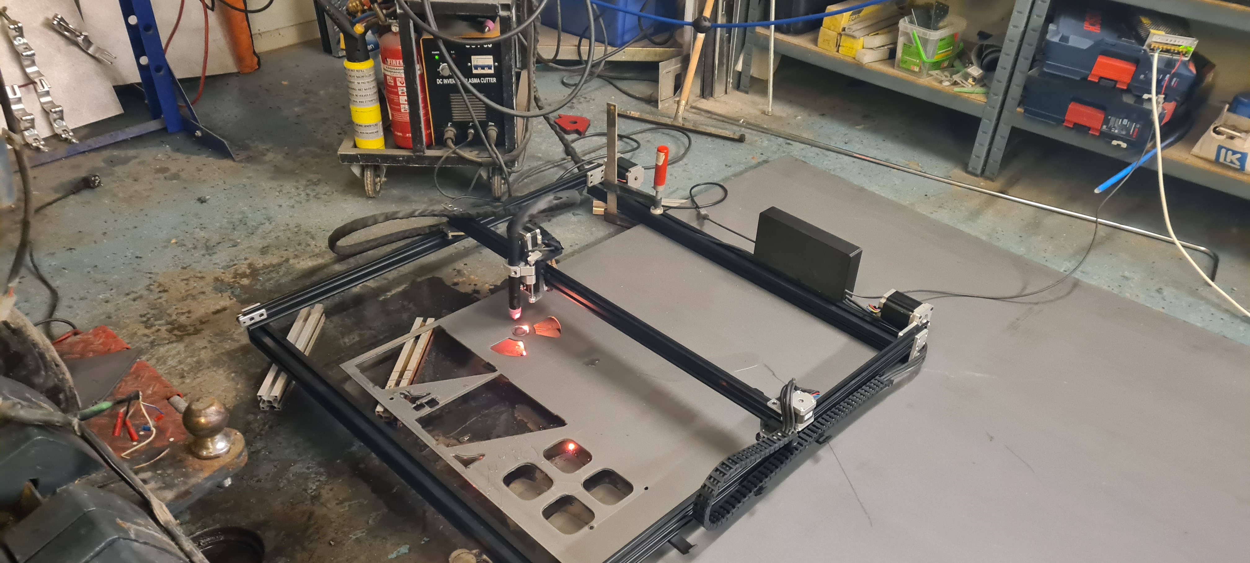
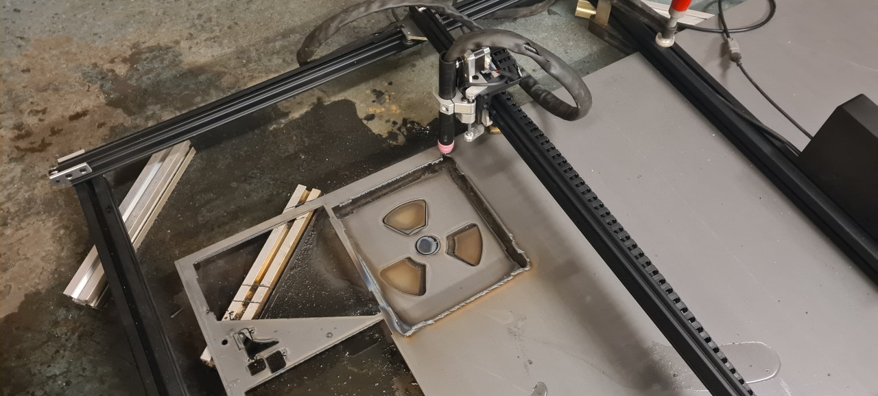
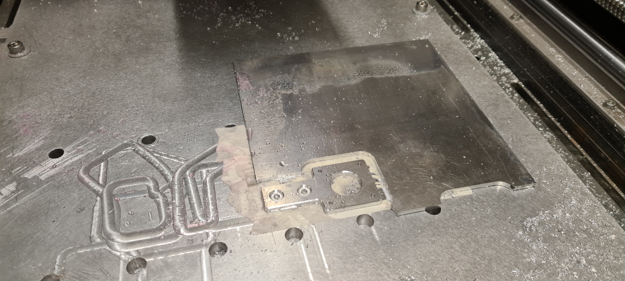
I did manage to pick up a 3mm steel sheet during lunch break and this is what the CNC plasma is going to cut the first parts from.. if it ever works.

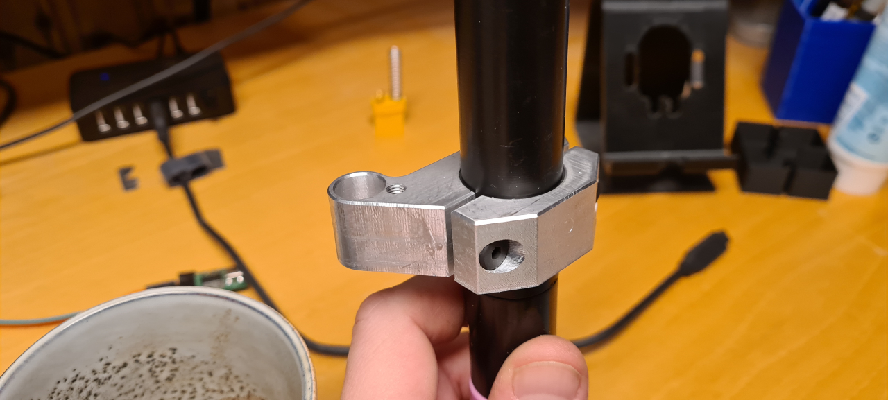
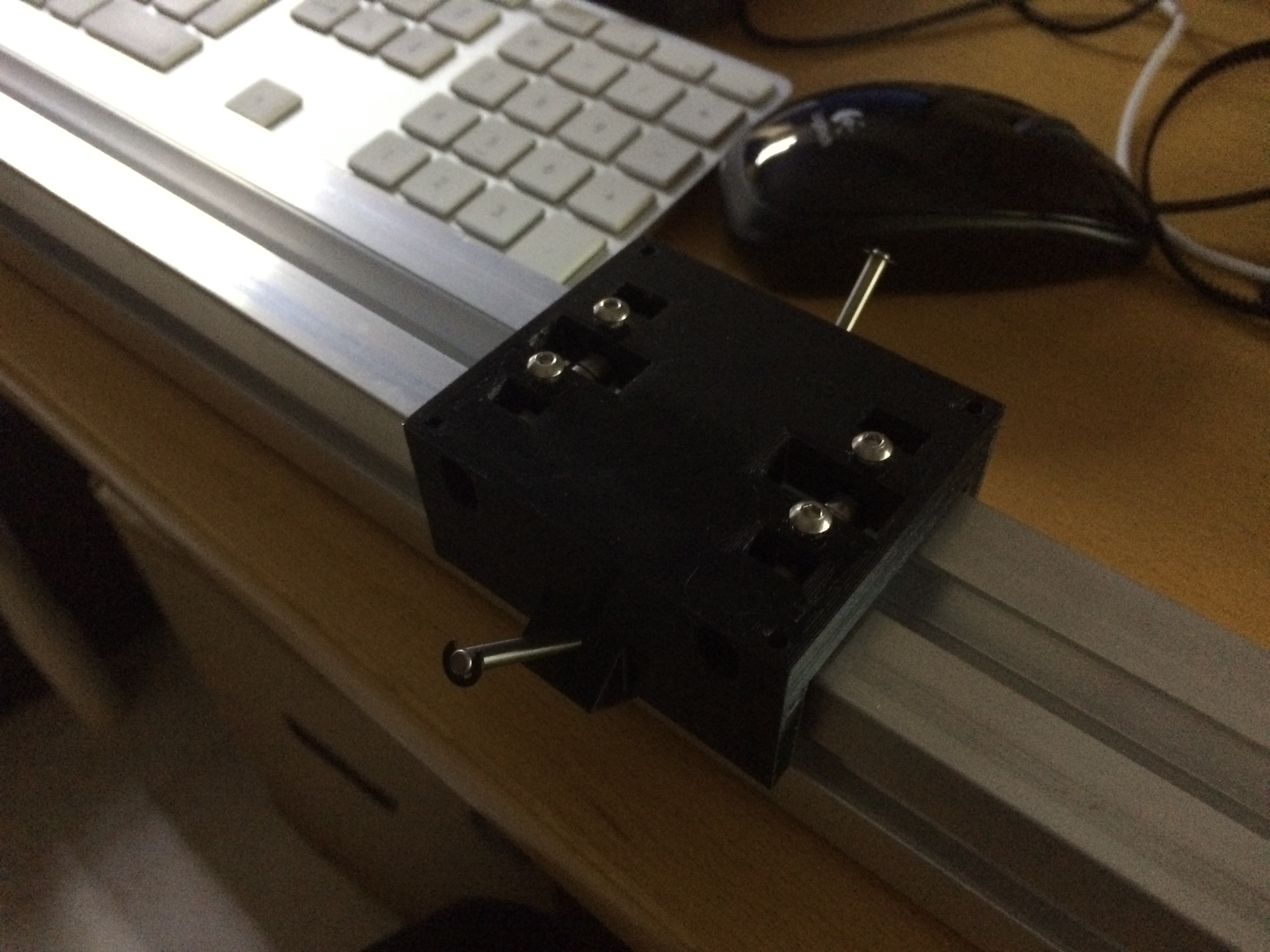
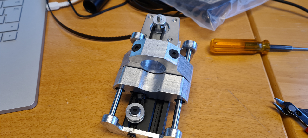
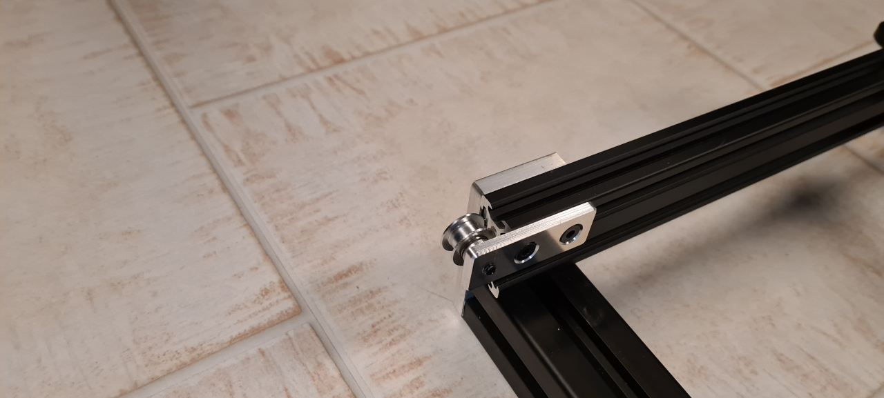
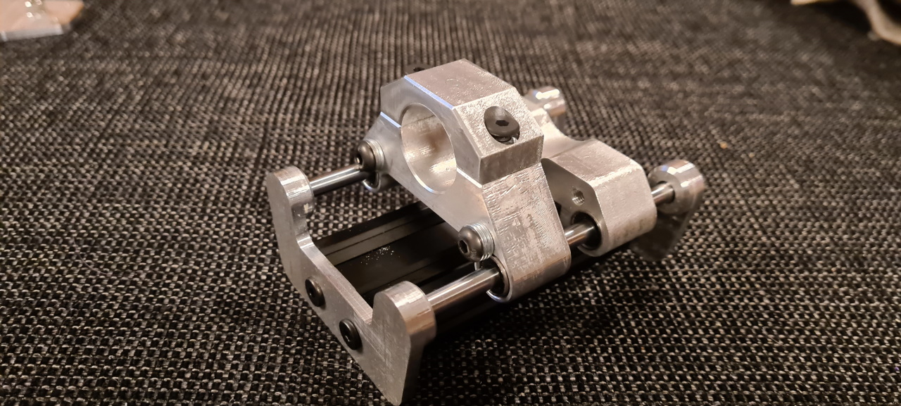
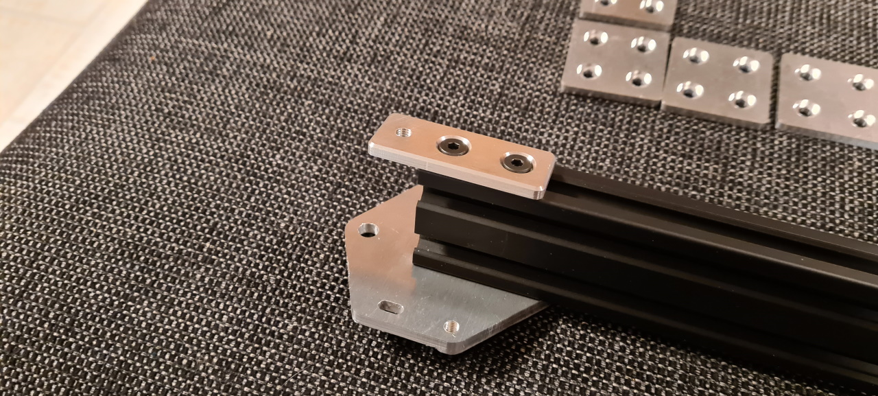
After making the clamp this is what the torch holder looks like. Fits perfectly!

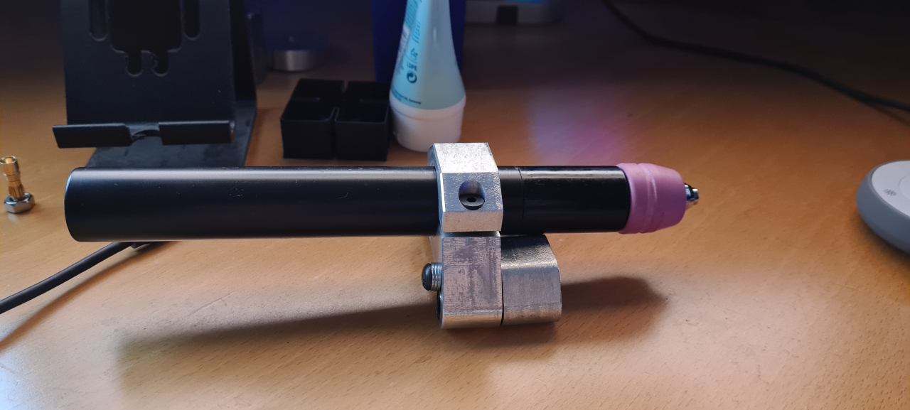
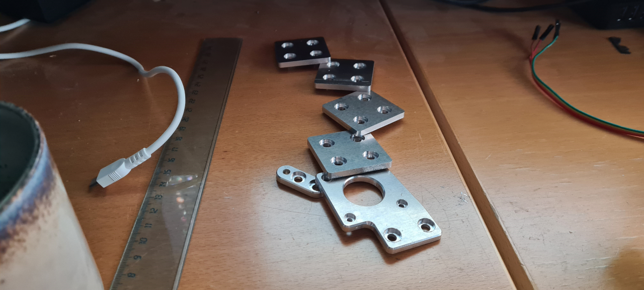
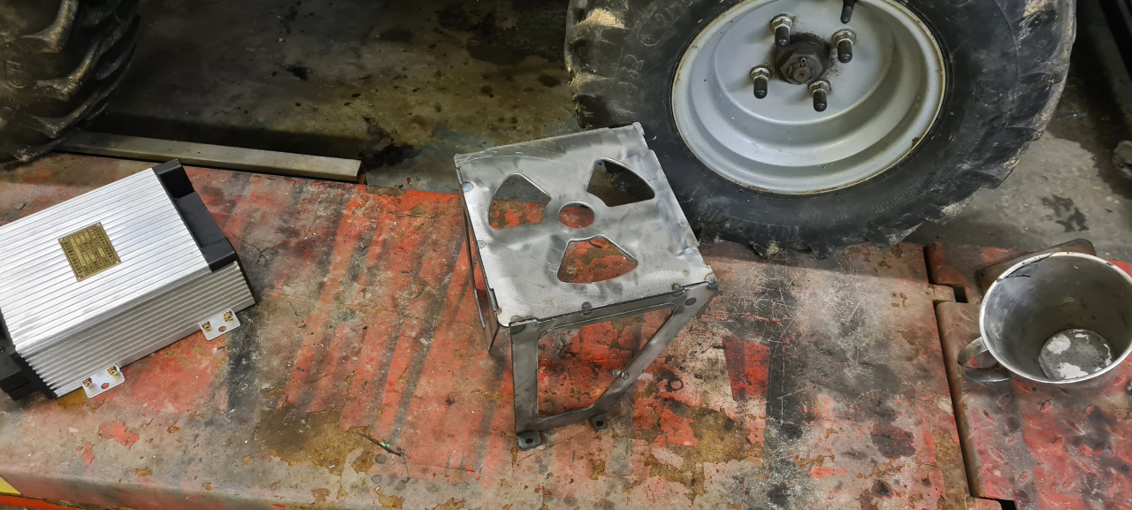
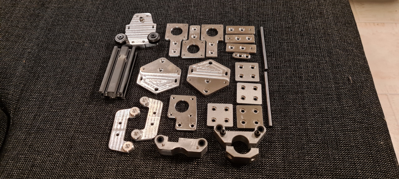
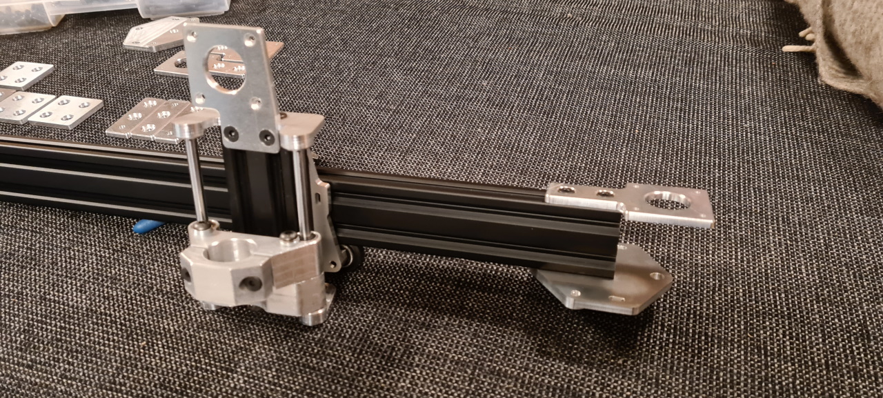
So, these three parts are what I managed to produce today. They are however the most complicated parts to manufacture by far and the only parts needing operations on more than one side, so the rest of the parts are going to take much less time to manufacture.. So, I’m pretty happy with what I managed to do today..

Stay tuned for the update tomorrow where the Z axis will hopefully be completed and the manufacturing of the X gantry at least started..

CNC Plasma – projektstart

För att kunna bygga vidare på barnskotern behöver jag lite precisionsskurna plåtbitar för att bygga drivaxelhållaren bland annat. Tidigare har jag fräst ut mallar och handskurit med plasman runt dessa – men allvarligt, hur roligt är det? 😉

Sedan jag upptäckte hur smidigt det är att plasmaskära metall har tankarna lutat åt en CNC-styrd plasmaskärare, och när jag nu behöver utskurna delar passar det ju bra att börja bygga.

Hittade billiga 40x40mm aluminiumprofiler från Tyskland, egentligen menade för fästanordningar för solfångare, men de duger nog till en plasma. Tanken är att bygga en skärare som man placerar ovanpå materialet som ska skäras ut. Arbetsytan blir lite mindre än en meter i kvadrat, så jag kapar till aluminiumprofil i enmeterslängder. Första steget är att bygga en ram till det hela, och här får 3D-skrivaren hjälpa till för att skriva hörnbitar:

Photo-2016-03-10-19-04-32_2303

Eftersom att detta ska bli ett budgetbygge utan motstycke så kommer jag att testa med elektroniken från 3D-skrivarprojektet. Jag behöver ju inte bygga en ny 3D-skrivare nu sedan jag bytte till optiska ändlägesgivare i kosseln så att den blev lite pålitlig. 😉 Någonting som drar iväg i pengar fort är linjärlager, så jag tänkte inte köpa färdiga sådana. Efter lite funderationer och CAD fick jag till slut ut en prototyp till linjärlager som kan fungera:

Photo-2016-03-10-21-39-43_2304

Photo-2016-03-10-22-15-06_2305

Jag hade en hel drös 8x4x3,15mm kullager sedan tiden jag sålde elmotorer, och passade därför på att bygga vagnar med just dessa lager. Skruvarna upptill är för att justera läget i höjdled på lagren som löper på profilens ovansida och därmed förspänna vagnen. I mitten sitter lager som kommer att avlänka remmen uppåt, och mitt på vagnen kommer det att sitta en NEMA17 stegmotor som driver vagnen. Denna prototyp hade några svagheter som version 2 (som skrivs ut just nu) rättar till, och den tror jag blir tillräckligt bra att bygga på. Axlarna på sidorna sitter i lager som håller vagnen fast på profilen genom att löpa i vinkel mot sidourfräsningens kant.
Resultate blev bättre än förväntat. Riktigt glappfritt och löper ruskigt lätt på profilen. Enda nackdelen är att vagnen kan vicka sidledes, men eftersom att det kommer att sitta drivning på båda sidor av gantryt så ska det inte vara något problem. Det fungerar dock inte för vagnen på X-axeln, så dit måste det konstrueras en stabilare vagn..

Fortsättning följer.