Battery mouting solution, work in progress
Svara

So, I’ve been repairing quite a lot of ebike batteries and to be able to re-use the old cells I need to get rid of all the nickel strips and spot welds that are on the cell poles. So for I’ve been using a side cutter to cut everything off to my best ability and then a dremel tool to grind off the remainder. The problem with this is that it’s quite messy and there’s a big risk of damaging the cells if grinding to much.
After wathing a youtuber make a servo-driven tool to cut the welds off 18650 cells I thought I’d give it a go, so I made a quick design in CAD.
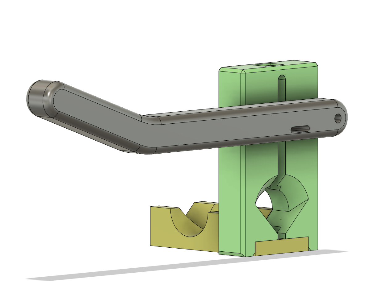
It’s kind of a gilloutine with a cradle to support the battery cell and a grinded cutter (stump from a MGN-12 rail) that slides in a track.. I’d thought I’d see if a 3D-printed tool would suffice.
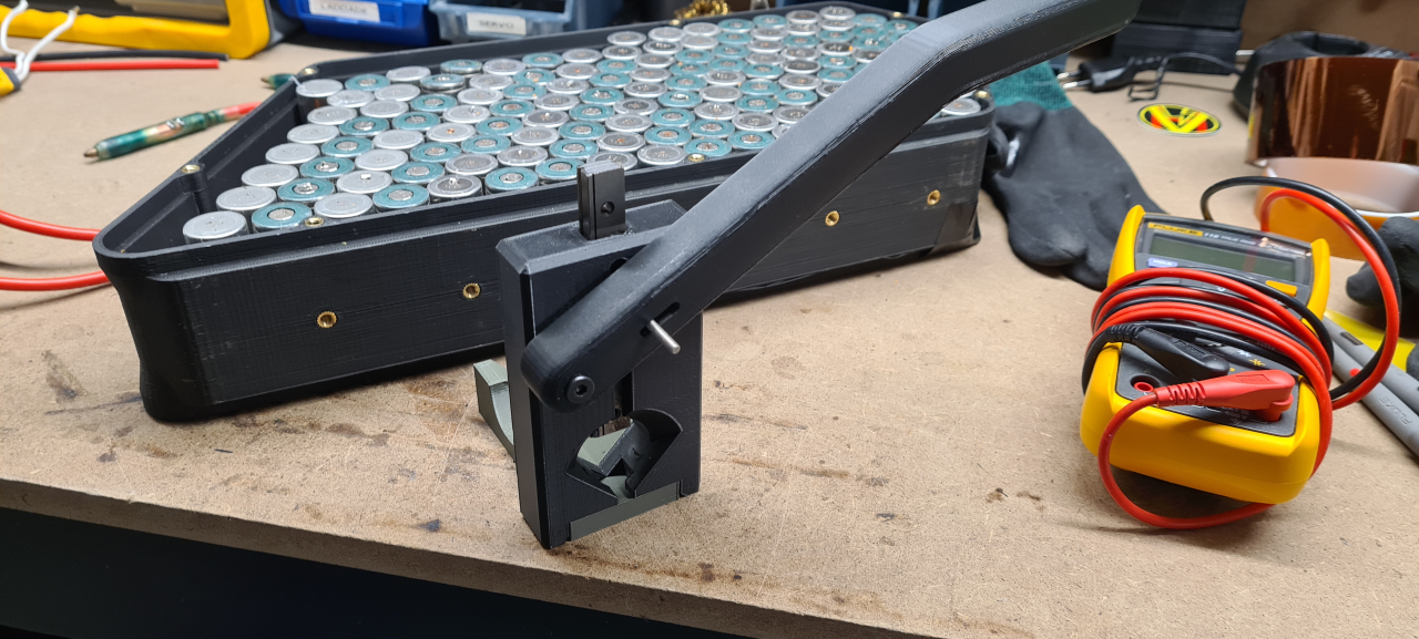
So, that’s what it looks like.
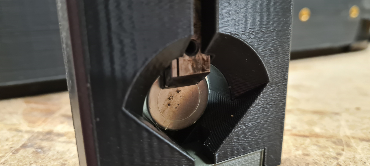
You slide the battery in as far as it goes, apply some pressure to keep it from sliding back and depress the handle.
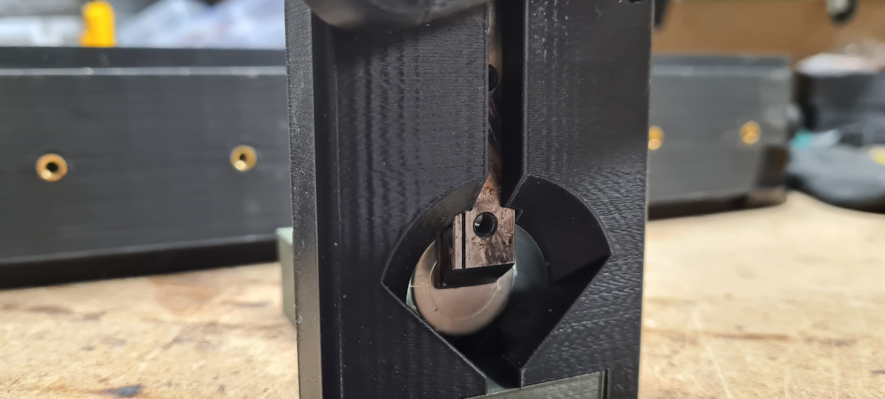
And it cuts all the crap from the cell cap. It works fairly OK, I might need to re-grind the cutter to be more aggressive though.. but as for now I’m happy with the result. It’s on par with the grinding wheel without all the metal dust flying everywhere. Some welds and nickel strips take quite a lot of force to cut off though so we’ll see how long this tool’ll last.
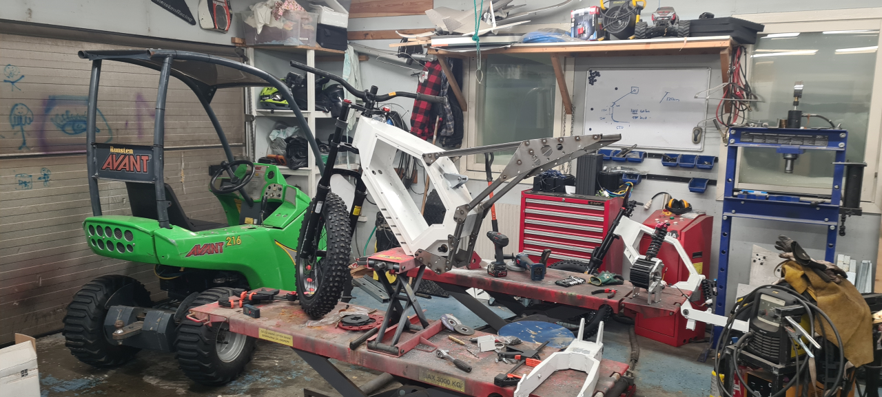
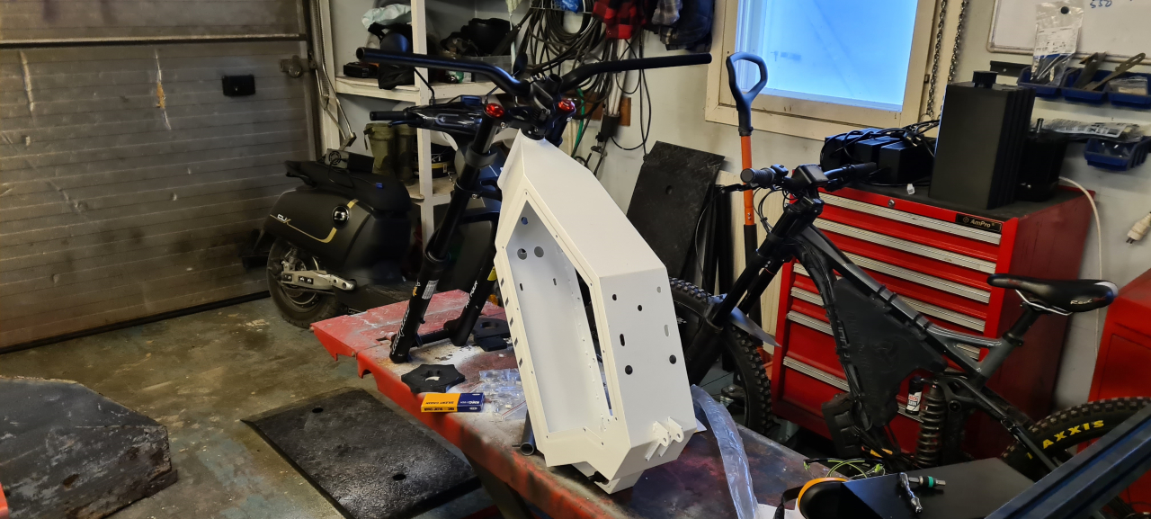
So, it’s been a while since I updated the project but it’s been a slow progress.
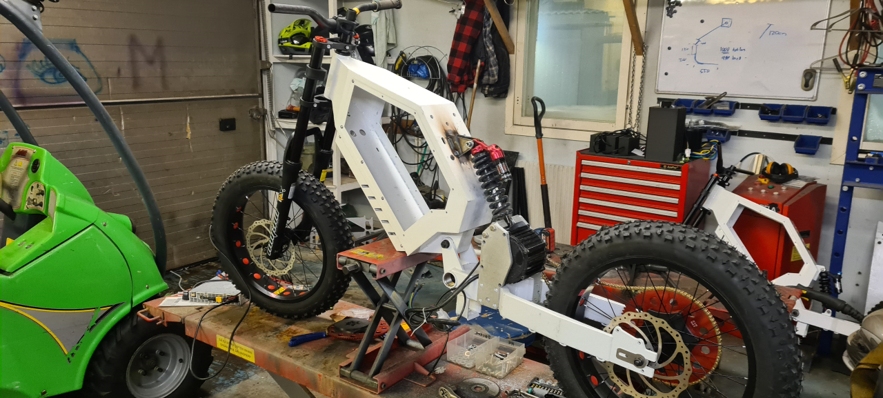
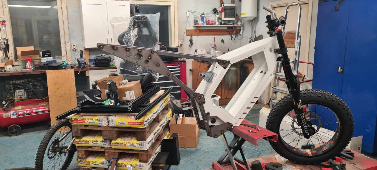
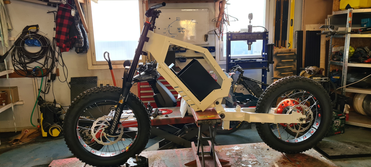
Started by building a mockup for the subframe to test fitment and how it’d look on the frame.
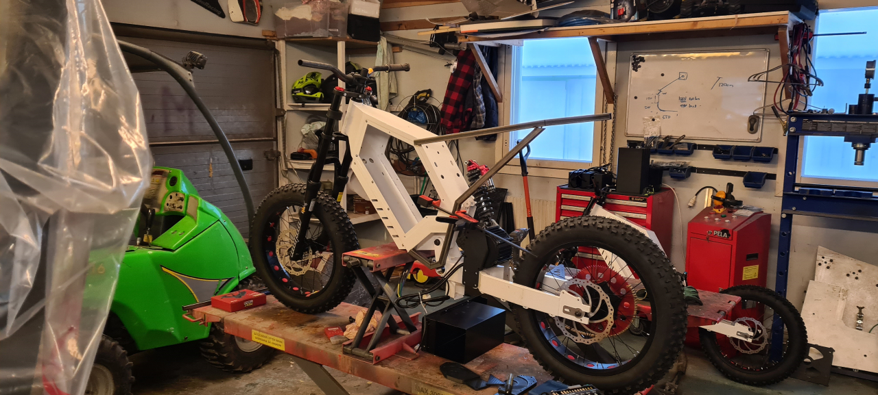
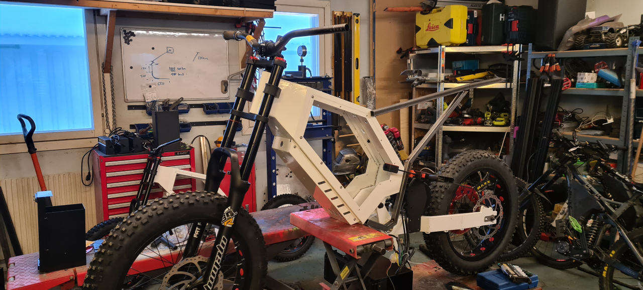
I’m pretty happy with how the mockup looks and fits on the frame, and it seems to be sturdy enough and kind of not too heavy (this isn’t going to be a super light-weight bike anyhow) so, on we go.
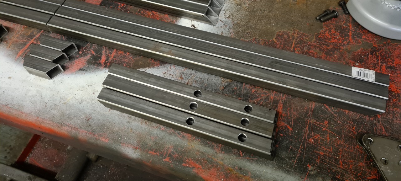
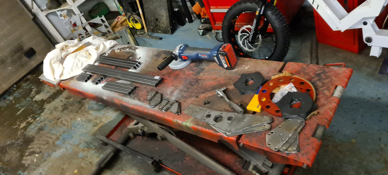
After having upgraded the CNC plasma with a better Z-axis it’s good to cut steel sheet with pretty good precision, so I cut the brackets needed for making all the subframe parts from 2mm steel sheet.
The result is pretty awesome for a low-cost DIY contraption..
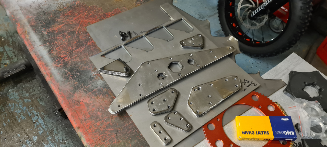
After a little bit of polishing with the grinder the final result is more than good enough.
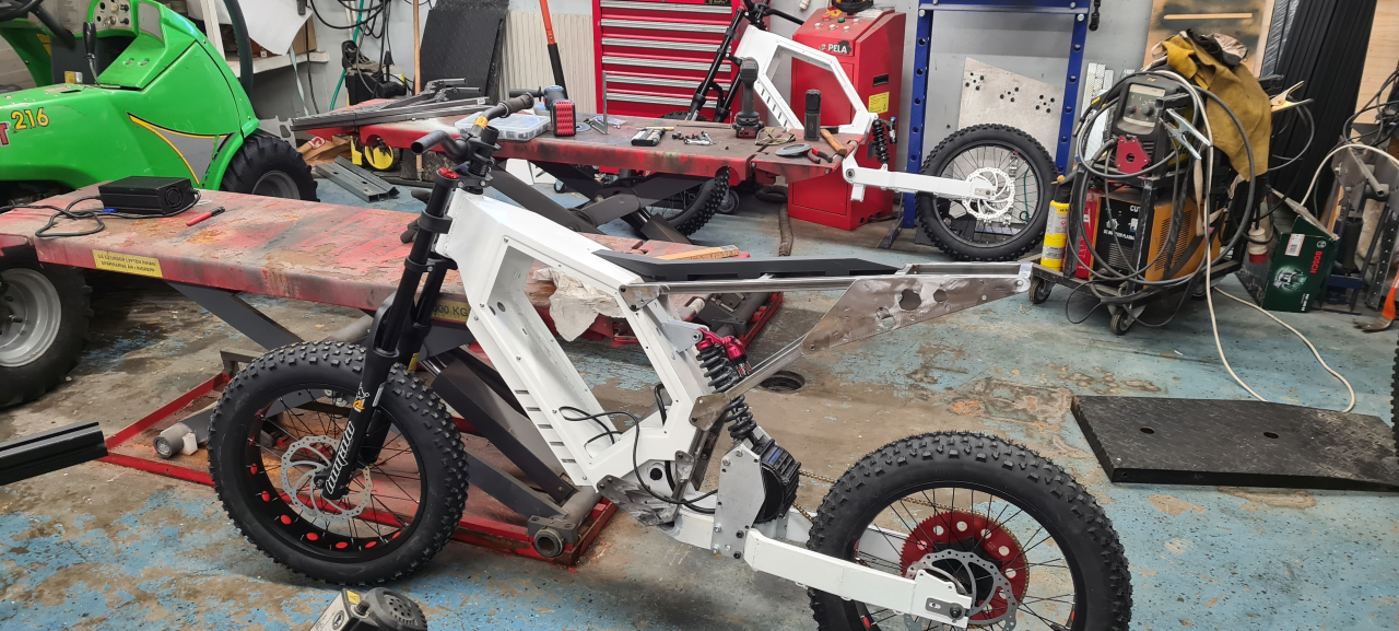
Unfortunately the 20×20 square tube mounted on the side of the frame interfere with the rear shock, the way I were planning on mounting it so I needed to come up with a new bracket.
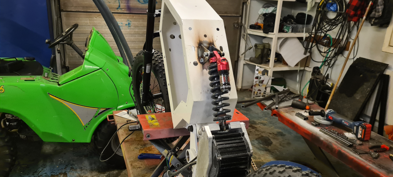
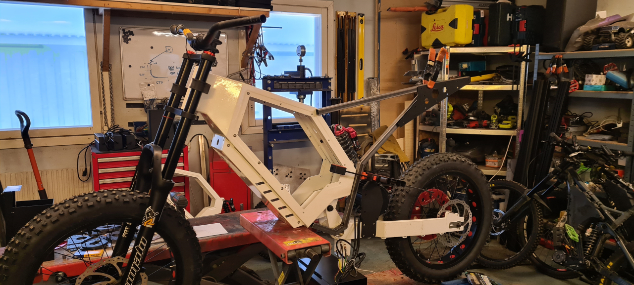
So I cut a couple of “ears” from 3mm steel sheet and welded the upper shock mount onto the frame. Now the stance of the bike is decided and it feels pretty OK.
The motor/shock mount is easily removed from the bike with just 9 M8 bolts. This is great for service and painting later on. If I may say so myself it looks frekkin’ awesome! 😀
Making the subframe
I decided to make the subframe from 20×20 square tubing as it’s strong enough, not too heavy, cheap and easy to get.
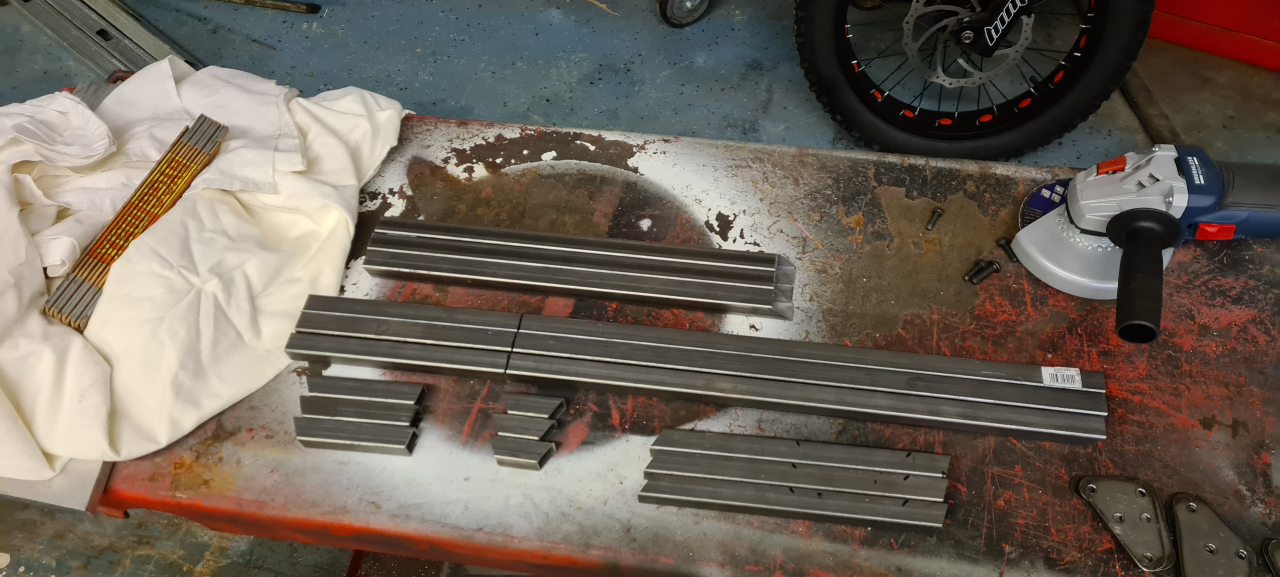
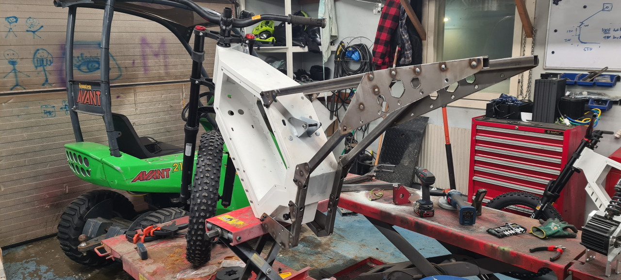
When this was done I just had to quickly weld everything together, drill and tap the mounting holes on the frame and make the joining parts for the subfrtame. The subframe goes under the bottom of the frame to be able to fit the footpegs.
Battery and seat
So, that’s about where we are for now. What’s left is a few fairings, the seat, battery and electrics.. (And the brakes of course)
While the 3D-printer is making seat parts I’m finishing up the battery.
Well, that’s all for now. To be continued.
To be continued..
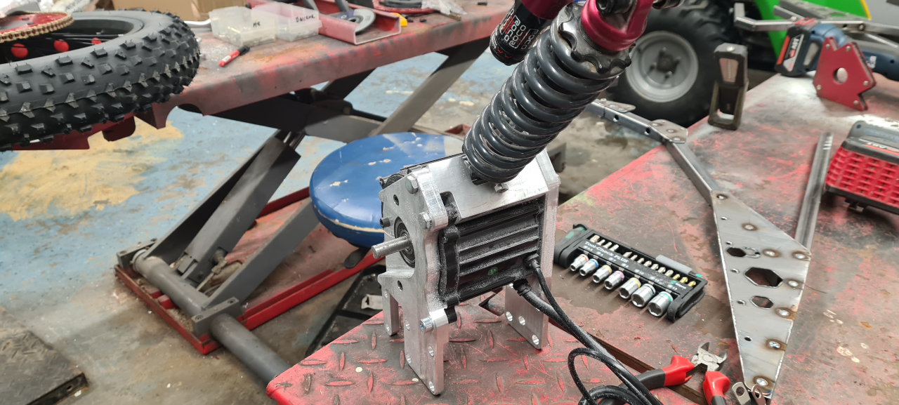
So, since recovery from the fatigue syndrome is super slow so will updates on the project be. That’s just due to most of my afternoons being spent resting and trying to get the brain to recover. But some progress has been made lately, both recovery- and project wise.
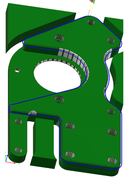
I’ve iterated the motor mounting plate design a bunch of versions and am pretty happy with it. Time to make some proper parts.
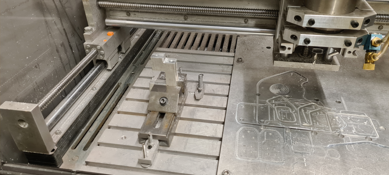
After some CAM-work in Fusion360 I cut some sheet aluminium and got to milling.
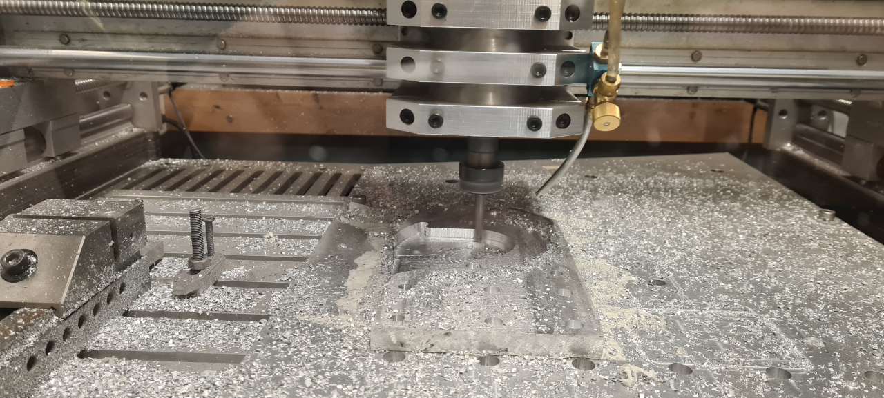
The mill really makes a mess throwing shavings everywhere, but since I built the enclosure at least it doesn’t fill the entire workshop with metal shavings. 🙂
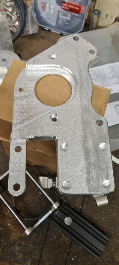
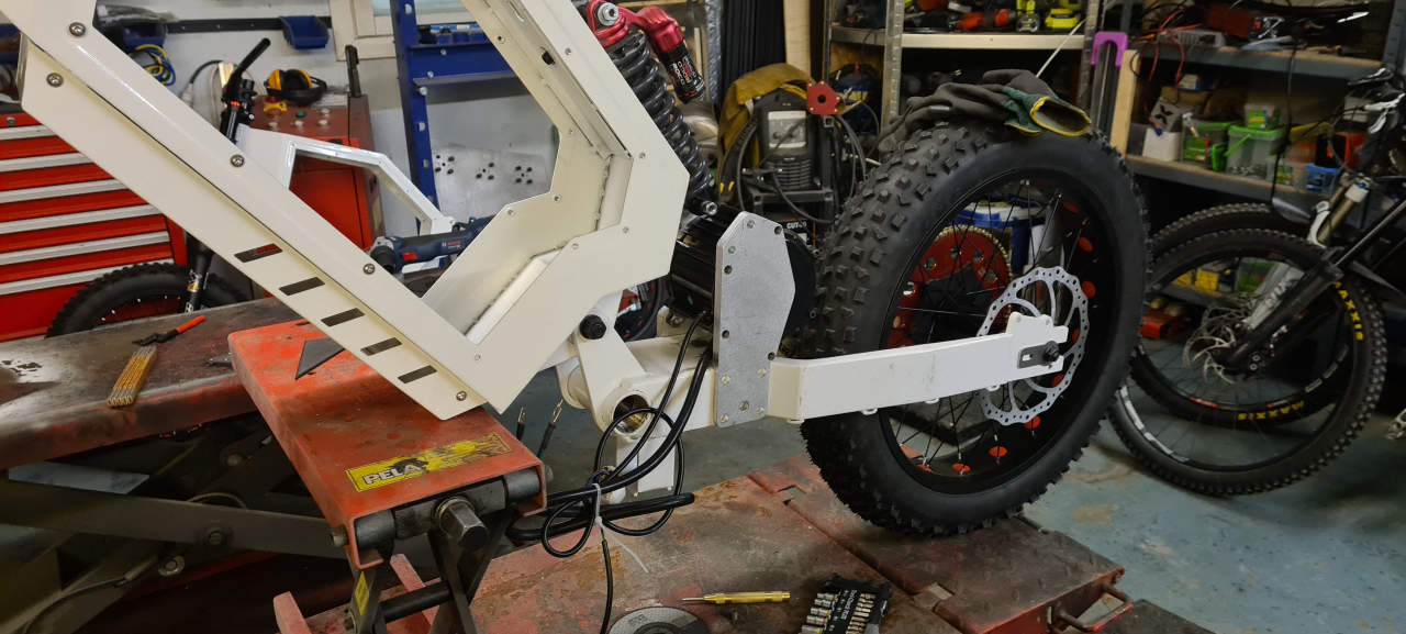
The result when milling aluminium is pretty amazing. This part looks even better IRL than in the pictures and being made from 13mm thick plate it’s super sturdy!
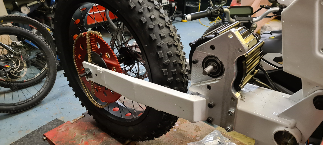
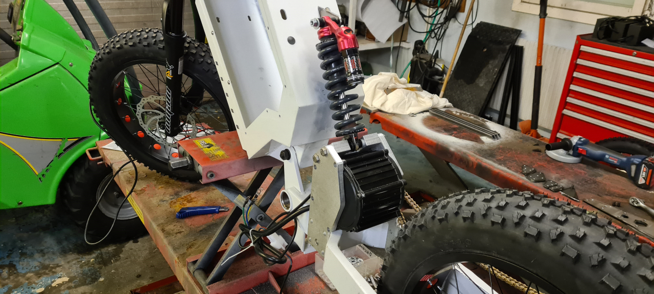
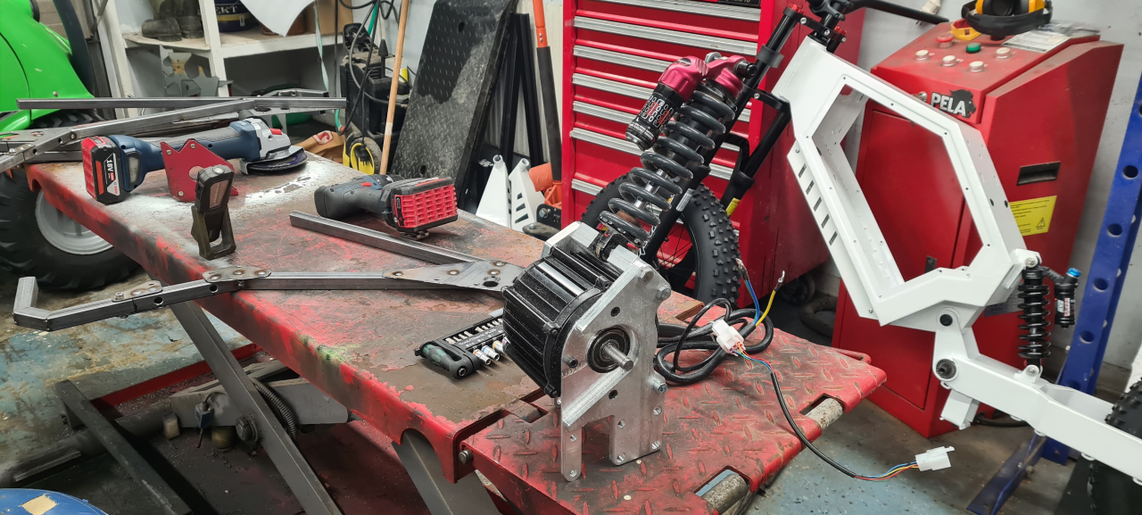
Bolting it down to the frame and mounting the motor everything fits super snugly and I’m starting to question the decision to make a mounting plate on the rear side of the motor too since the motor seems rock solid as it sits now. Buuut, it’s better to make it to tough so we’ll make one just for the fun of it.
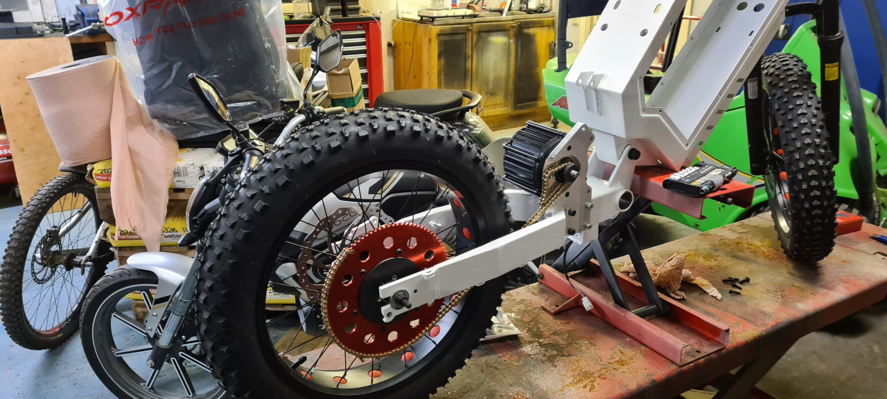
Test fitting the chain again with the proper motor mount. I’ll have to make one last prototype of the rear sprocket adapter but now I get proper clearance to both the wheel and the frame so the next adapter is just to get the chainline straight. Right now I’ve got the largest sprocket I’ll use mounted to make sure the chain doesn’t strike the frame in the worst case scenario.
I’ve been getting parts for the second bike aswell. I’m going to build it up to use as a template for checking the geometry so as not to mess anything up when customizing the bike. It’s a chinese clone frame so the geometry probably isn’t perfect to begin with but it’s good to at least know what I’ve changed when re-designing it.

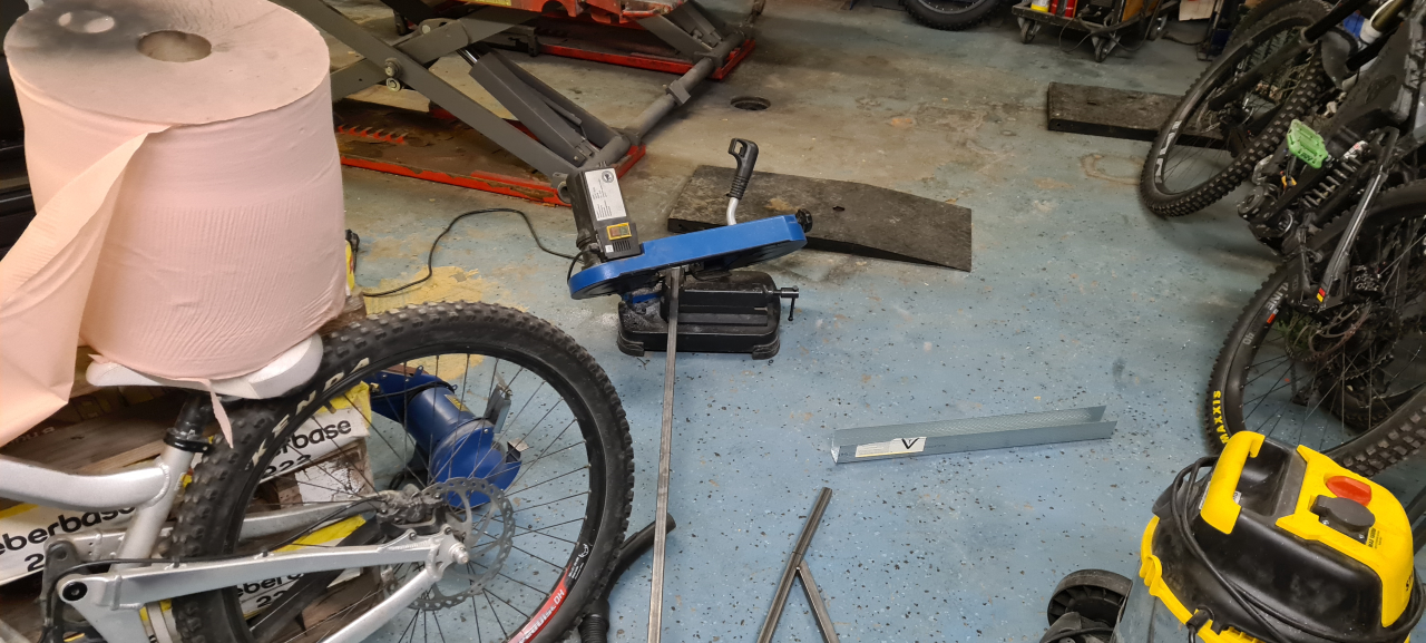
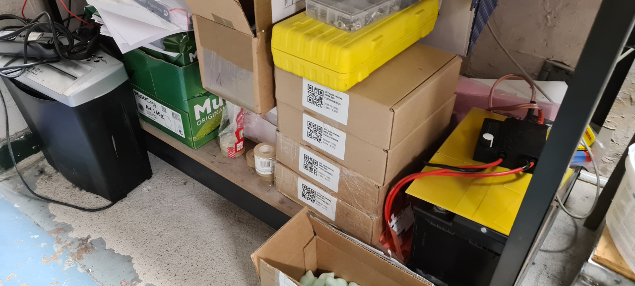
Winter is coming and right now the garage/workshop is a mess with all the projects and stuff that needs storing and protecting from the cold. It’s a bit annoying trying to get stuff done in there but it is what it is. I’ve got to move stuff out when using the plasma cutter that I need for the coming project of making a seat and upper shock mounts..
So, what’s next?
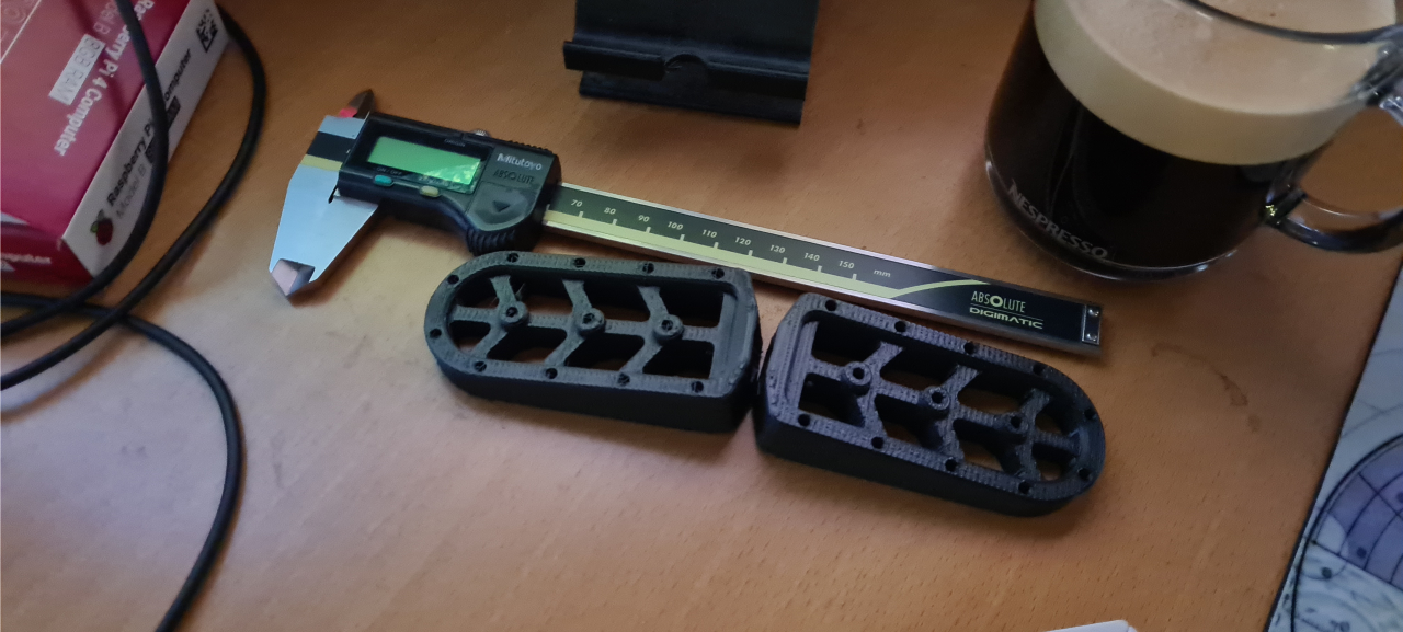
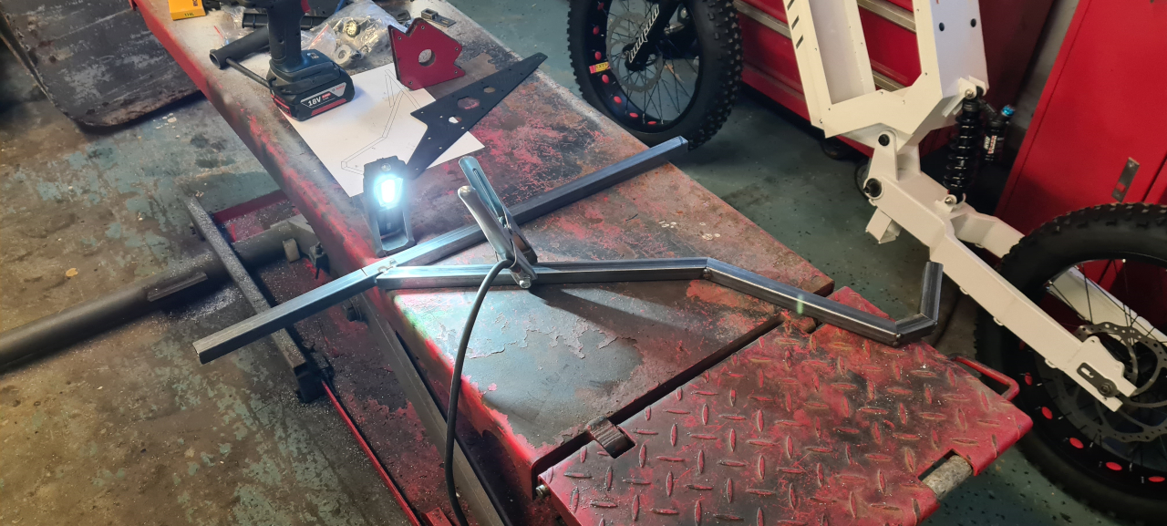
Since footpegs seem utterly expensive I’ve started mocking up custom footpegs for the bikes. I yet have not decided on how and where they should mount to the bike but I know I don’t want them sitting on the swing as the original pedals were mounted on the bomber frame.
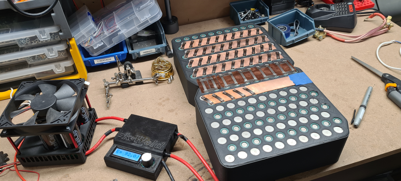
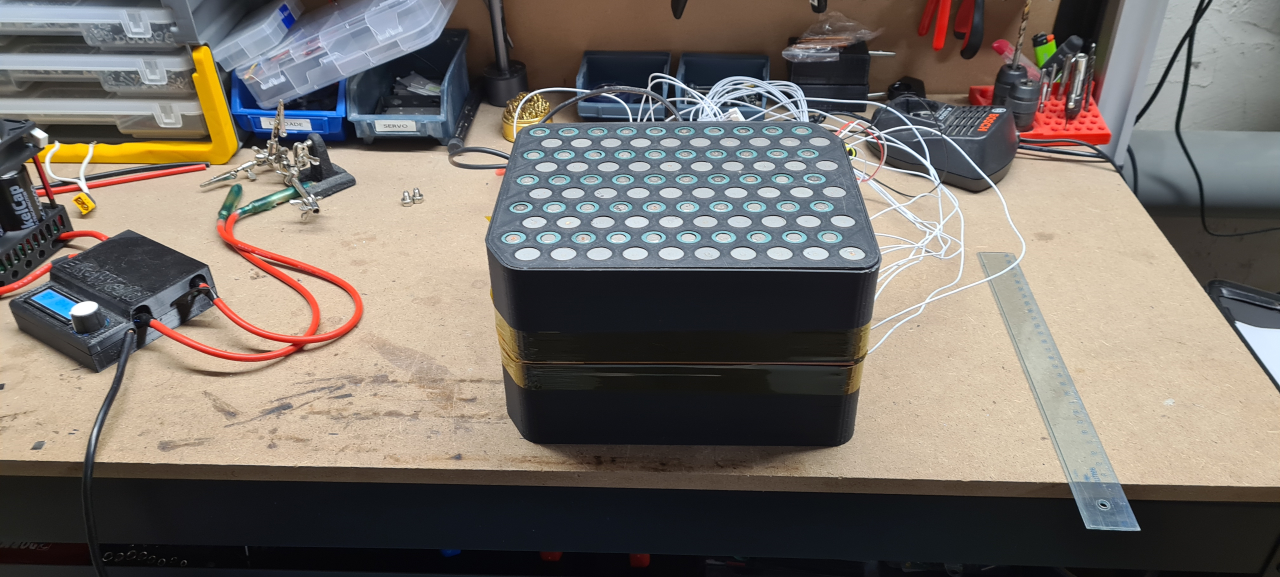
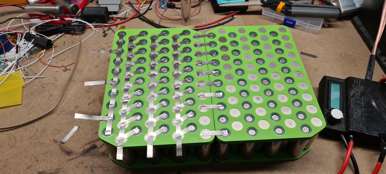
The 21700 cells have arrived so I’m looking at making the batteries for the bikes. It’s going to be a 20s10p pack made from Samsung 30T cells at 3000mAh and 35A.
For the first time ever the build is not restricted by the available space in the frame as the bomber box would fit a HUGE pack if filling it up. I’ve decided to go with 200 cells per pack due to cost and weight. This pack is going to be around 14kg just in cells so it’s going to be heavy enough as it is.
72v nominal at 30Ah yields about 2,2kWh which should let us have fun for at least 100km at a time I hope, of course depending on how we ride. =)
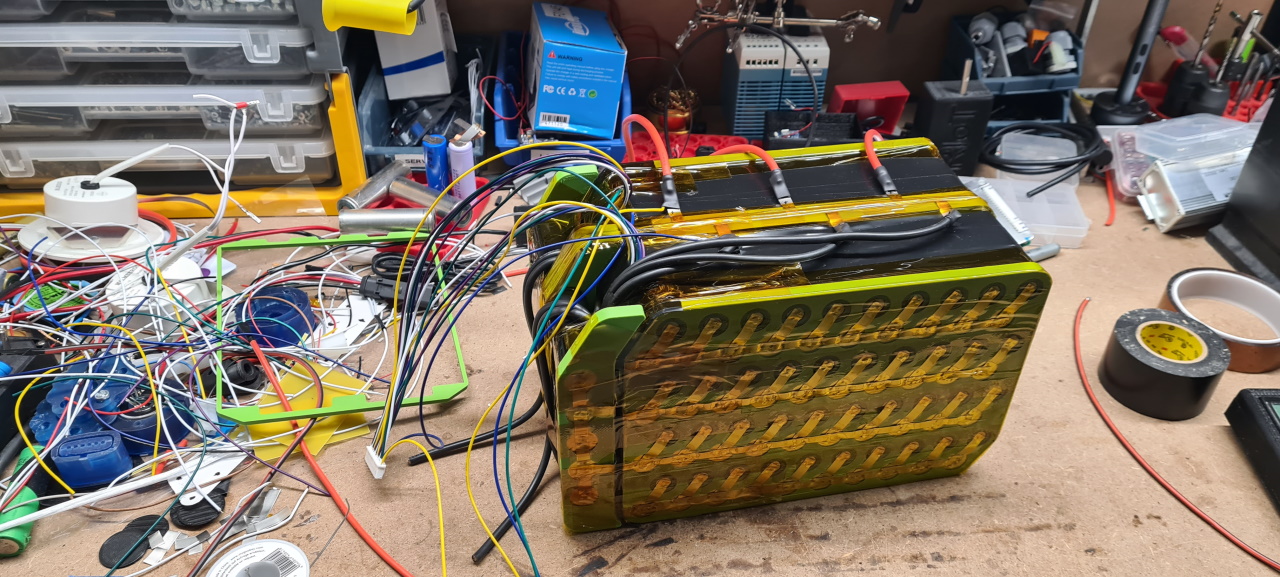
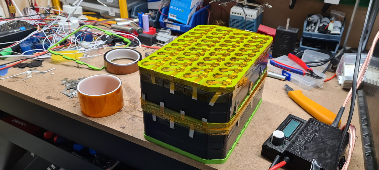
I’m using the same method of building the packs as I do on regular bike packs but as with the avant battery this is going to be a CU sandwich type pack as to be able to deliver 300A of peak current..
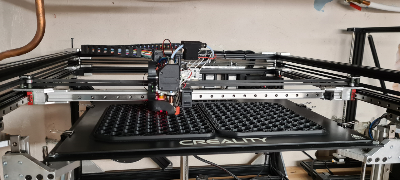
Here I’m printing the cell frames, three at a time, on my “Stoorn v2”-printer. The next step in the battery process is making cell spacers, measuring the voltage on the cells and starting to put the cells into the pack before welding.
I’ve ordered a pair of ANT 300A BMSes as I’ve used them on all my avant packs and am super happy with the way they work. I’m looking at getting some 10A+ 72v battery chargers to charge the packs in a reasonable amount of time but we’ll see what we end up using.
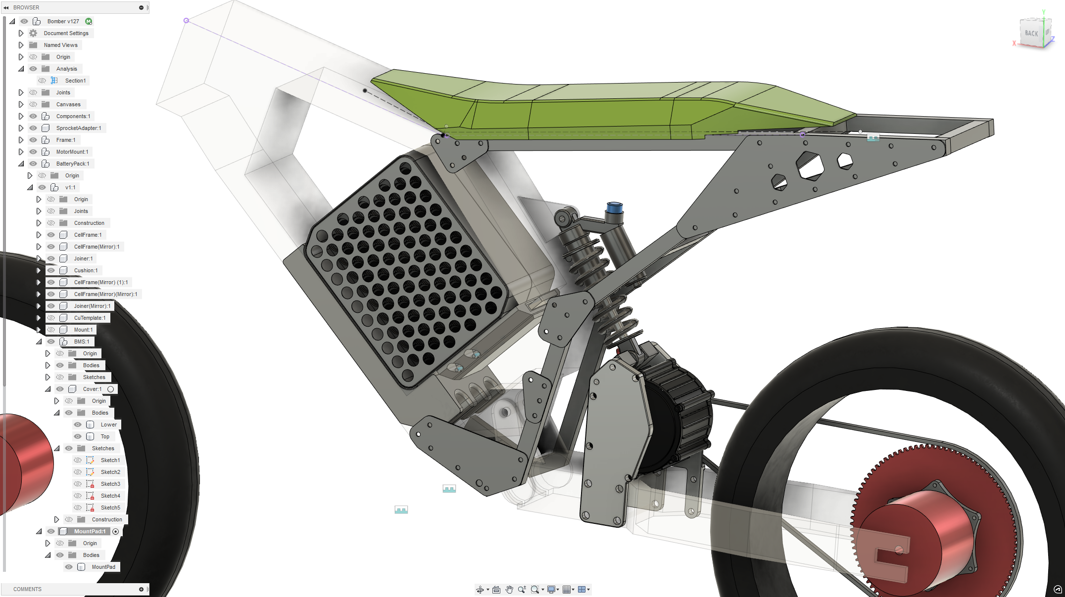
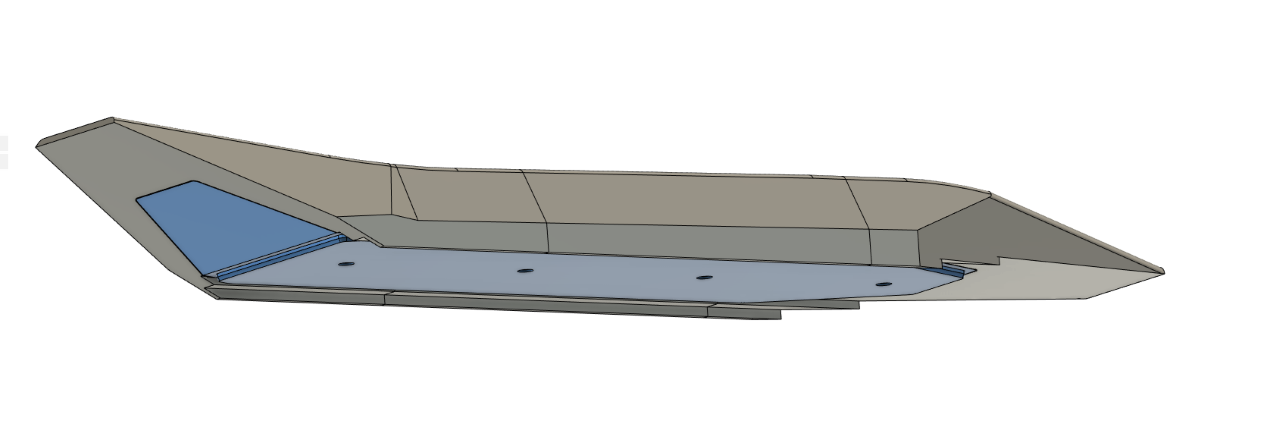
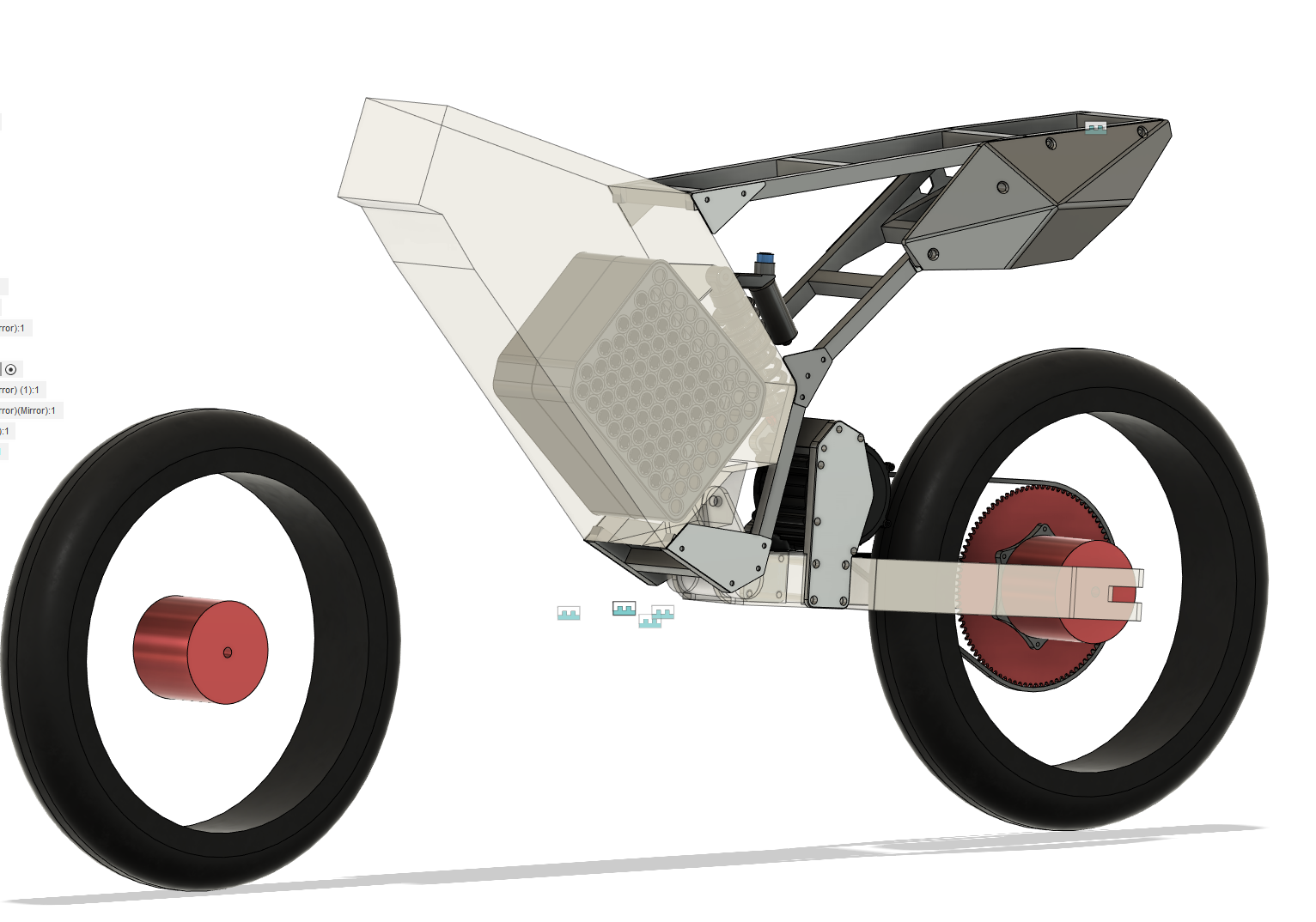
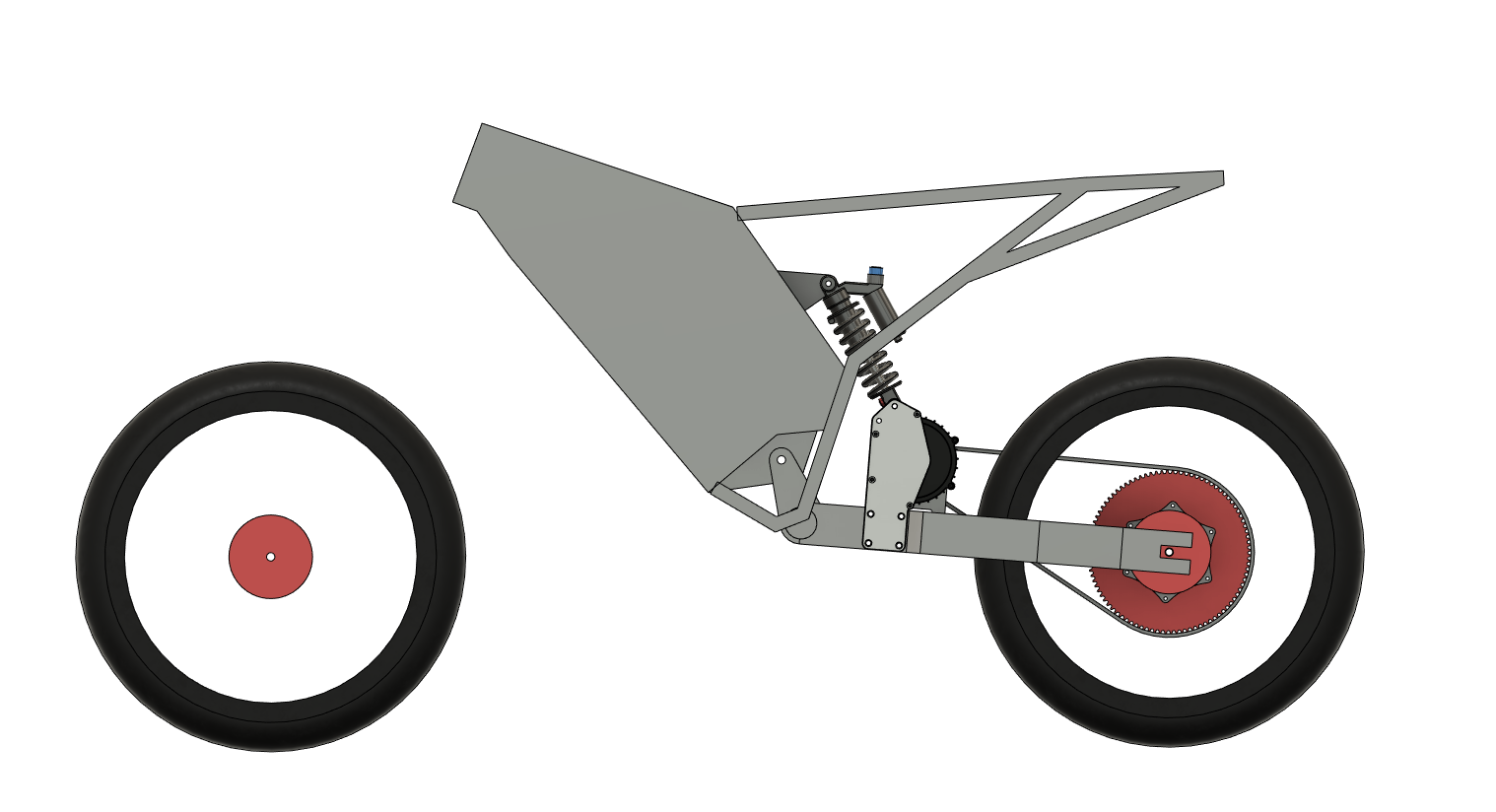
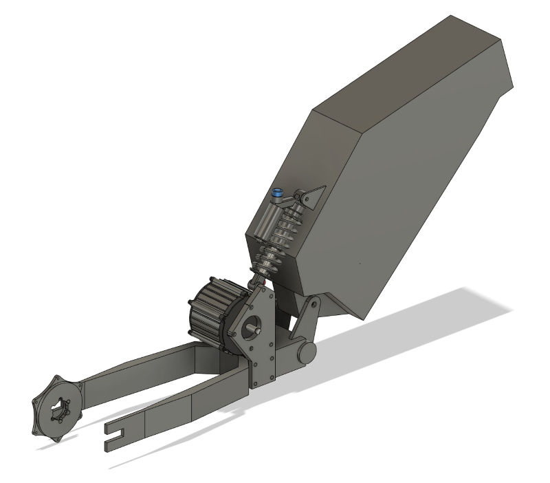
This is where the CAD is currently at. I’ve printed the first iteration of the back plate and am going to fit that on the bike today as I’m milling the adapters for the rear wheel.
I’m trying to make shorter and more frequent updates but as it is now the project stands still for huge amounts of time while I CAD and design and print stuff, and then I’m making progress that shows in a few days.. so I’m doing my best to keep everything updated.
Thanks for reading and if you’ve got questions or comments please post a comment on here or reach out on facebook, instagram or discord.
To be continued..
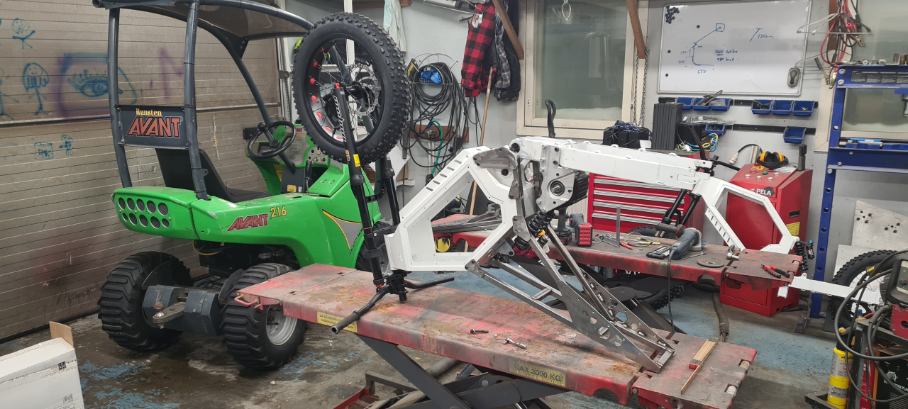
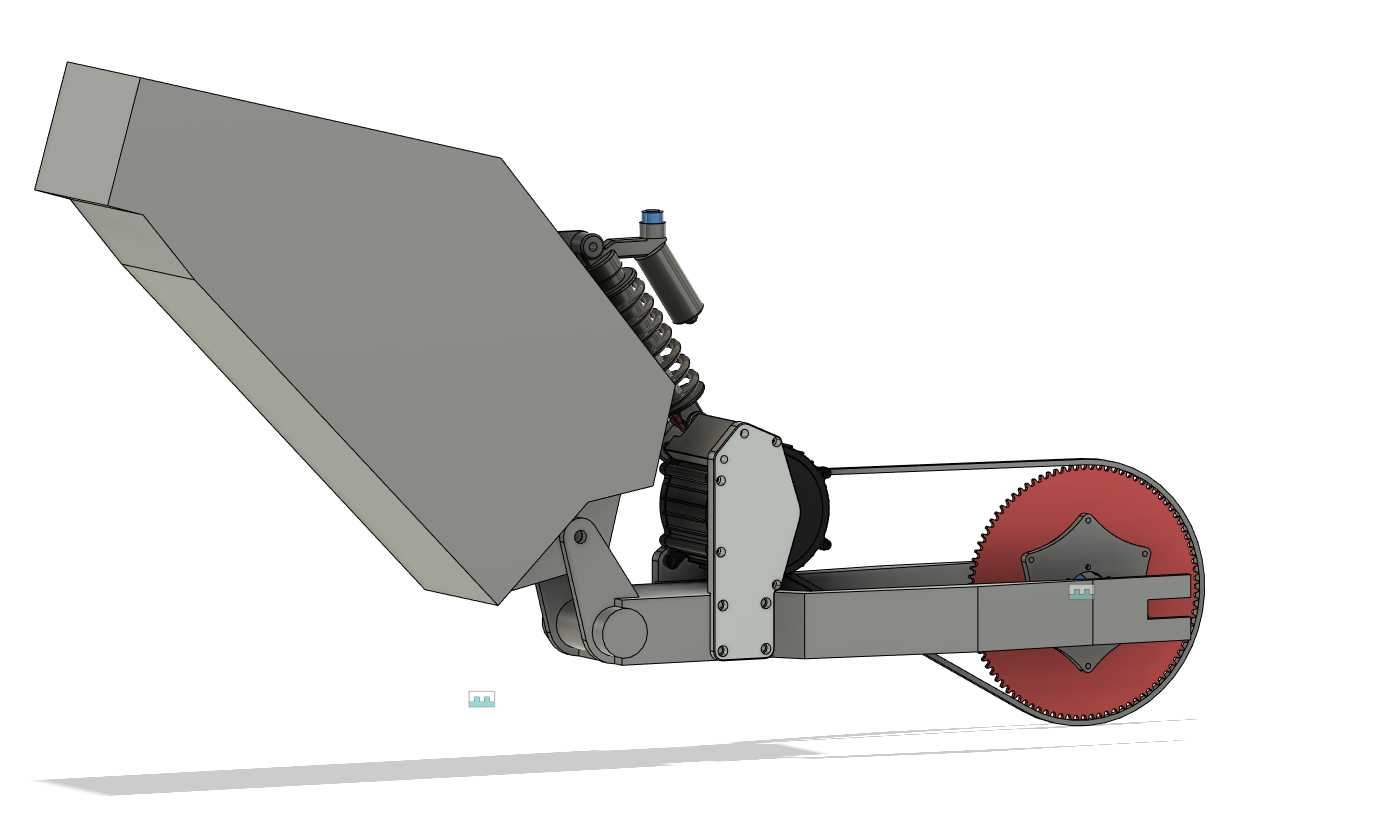
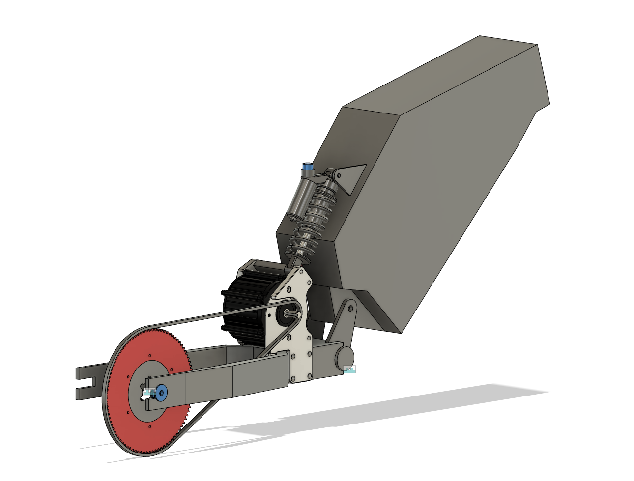
Having done the mockup for the wheels and mounted the brake rotors and made a mockup for the rear sprocket adapter the next step is mounting the motor.
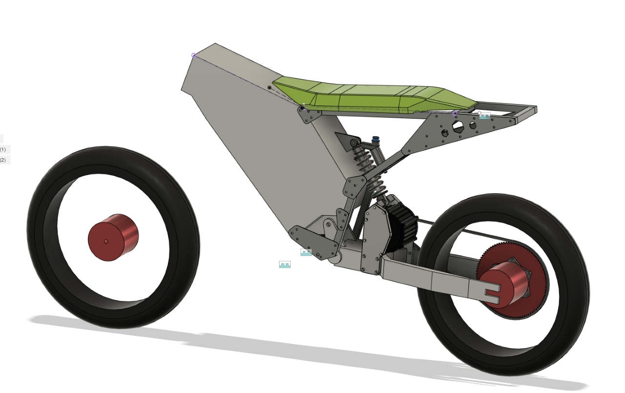
Since the frame is designed to fit a hub motor and we’re going to use mid-drive motors we need to figure out a good way to mount the motor on the frame. I’ve considered quite a few different positions for the motor but they all have drawbacks. I decided the best solution is to make a motor mount right in front of the rear wheel, making the shortest possible chain line while still keeping the motor as close to the pivot as possible as to limit the unsprung mass momentum of the bike. The tricky part is that this is where the rear shock sits.. So I started by mounting the 200mm shock I’ve got and made the bike sit in the fully extended position on the bench. I then removed the shock, cut the lower shock mounts off and did some measuring.. The CAD turned out like this.
There is going to be a bracket on the left side of the motor too but as of now I’m not sure wether to simply make a motor/shock bracket or to make a new custom endcap for the motor. The right bracket prototype is being printed right now and I’ll use that to check more clearances and get a better feel for the solution. In the CAD I’ve moved the shock all the way to the right to limit the forces on the M8 bolt that holds the shock but where it’s going to go is not yet decided. The upper mount might screw right into the frame or I’ll make it a part of the seat.
I’m going to try to make this modification without welding anything to the frame so it’ll be easier to reproduce if anyone else wants to build a similar “bike”.
TBC..
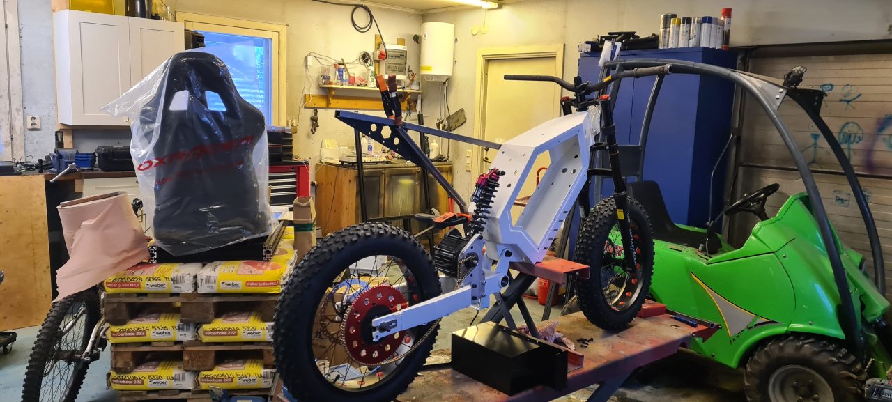
Winter is coming and last winter me and the kid agreed on needing fatbikes to ride on the snow..
Of course they’d need powerful motors enough to propel them through the snow and not bog down even when hitting deeper pockets of powder. At first I planned on building my own frames, but as summer came and went and I didn’t have time to get going I decided to get a test frame to start building on to see if our planned setup would pan out..
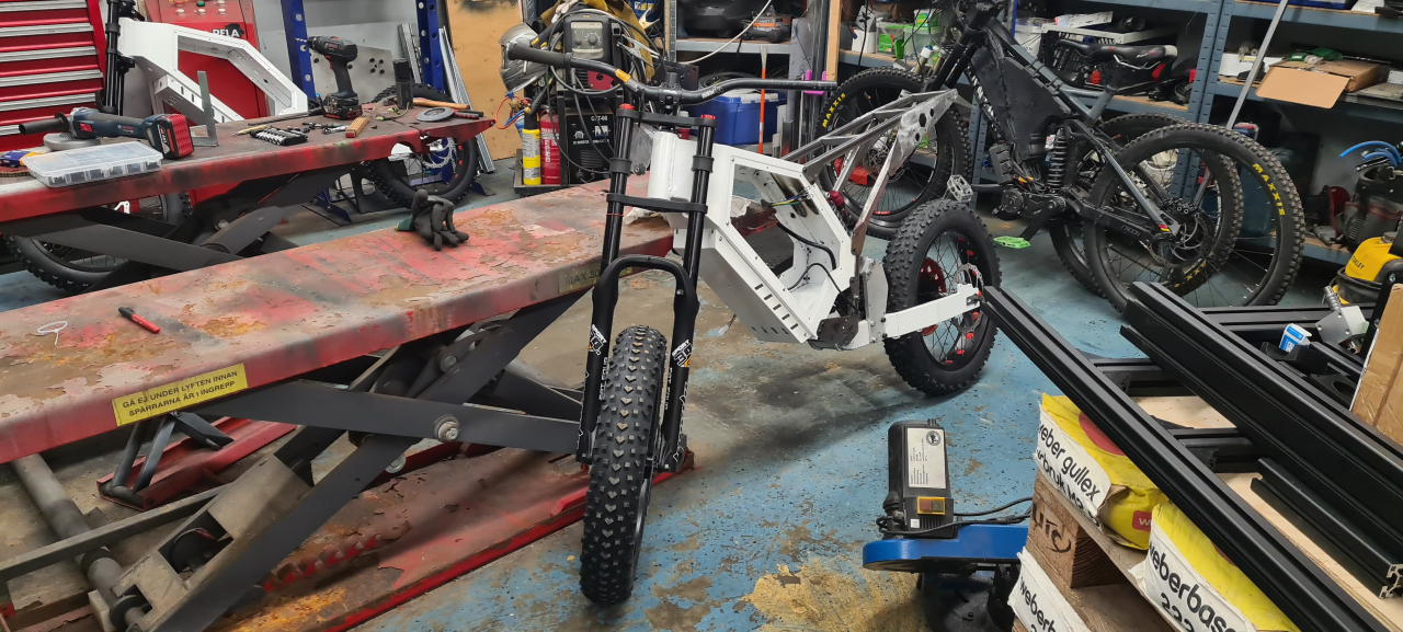
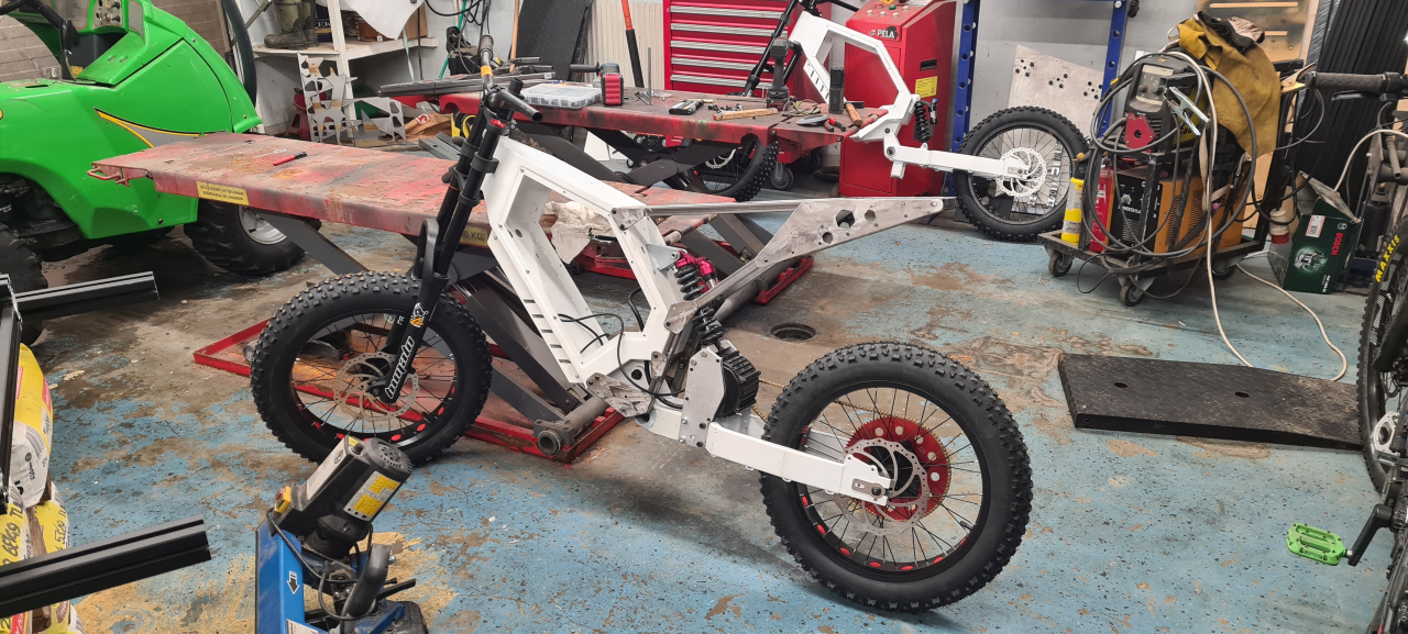
So, this is what I got:
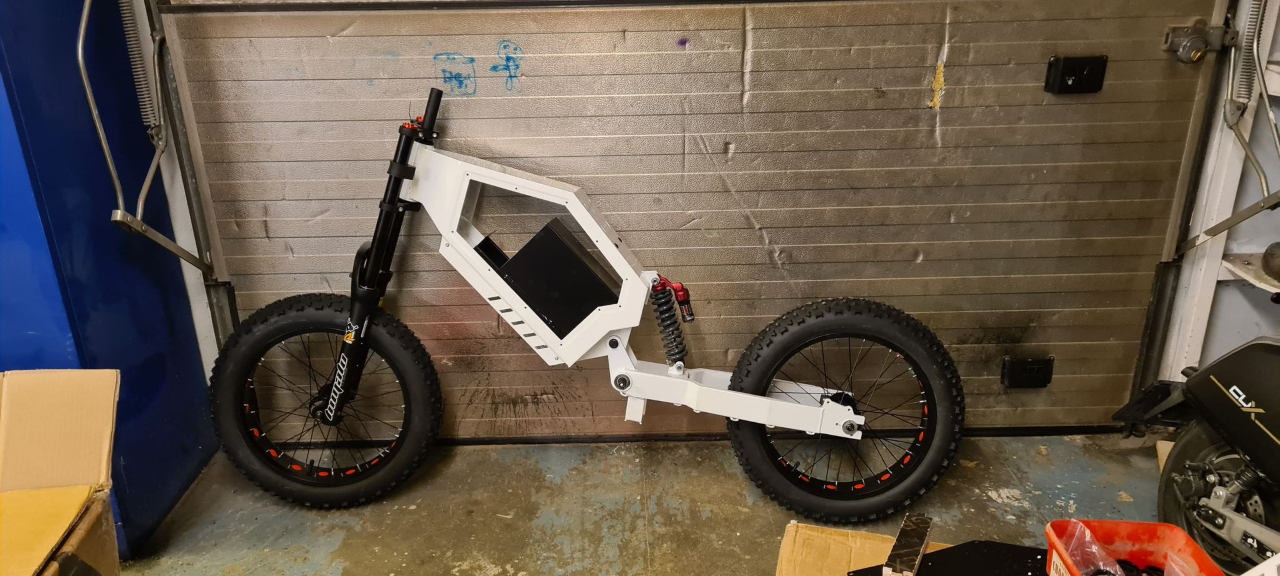
It’s a chinese clone of a “Stealth bomber” type frame, made entirely from 2mm steel, making it both heavy (20+kg) and sturdy. We’ve got 20″ fatbike wheels on there and personally I think it looks sick. 🙂
The rear suspension I just stole from another bike we’ve previously built and gutted, and the front suspension is a 190mm travel air-sprung fork made 100% from chinesium, but it still seems of rather OK quality.
To get enough power to have fun on these we’re going to use LightningRods BigBlock motors, good for somewhere in the vincinity of 14kW. We’re going to build a couple of hefty 72v battery packs with at least 30Ah capacity and using either ASI BAC2000 or BAC4000 motor controllers to translate the battery DC current to pure joy on the rear wheel.
And yeah, there probably won’t be any reason to put pedals on a bike like this, so we won’t. Footpegs’ll have to do. Since this frame is originally built for hub motors and we’re not using that there are modifications to be made. We’re probably going to fit the motor right where the rear suspension sits right now and move the suspension upwards. A single stage 219 chain reduction will translate the power from the motor shaft to the rear hub. Then we’re building motorcycle style seats to go on the bikes too, some kind of twist throttle, hydraulic brakes, probably have to make my own studded wheels, lights (since it’s mostly dark in the winter) and possibly a kickstand..
Well, that’s the plan. We’ll see how it works out and if we get to ride it this winter. As it sits now the frame, wheels and suspension is in place. I’ve got the motors and controllers but no batteries or other electronics needed. Next week I should get the chain and prockets to be able to start manufacturing adapters to mount stuff where it’s not intended to go and I’ll post updates whenever I get around to it.
First I’ll need to do some modifications to the CNC plasmacutter though to be able to precision cut the parts I need for this project, so that’s next..
So, early this summer season I did something really stupid. I replaced the brake pads on my ebike and took it out for a test.. Riding 50m on the street outside our house being a little bit too tired. The bike was in second gear, I thought it was in third so when I pushed the throttle it wheelied.. a little too much.. Tired as I was I slammed the brakes.. both of them.. so when the front wheel hit the ground it was locked sending me over the bars. Never let go so when the neighbor found me in the ditch I had scratches on the outsides of my hands, my elbow was bleeding badly and I had hit my head pretty bad which knocked me out for a bit. Since I was just going to test the brakes I was not wearing a helmet.. :/
When I regained consciousness I was pretty out of it and after talking to my brother a bit asking the same question over and over he sent me off to the ER. A few stitches, a couple of shots and a complete brain scan later I got to go home with orders to REST.. which of course I did not.
My daughter turned 15 this summer and she got an electric moped for her birthday. Since the bike can fit two batteries I of course had to build one from cells I’ve reclaimed from old scrap ebike batteries..
These are Samsung 30T 3000mAh 21700 cells, good for 35A a piece.
Since the moped and charger says 60V I built this 16s10p pack which would fit the battery compartment in the moped easily.. but then I checked the voltage of the charger and realized it’s a 17s system.. :/ So, I had to put an extra 10s cell on top of the pack making the fit pretty tight, but it still works.
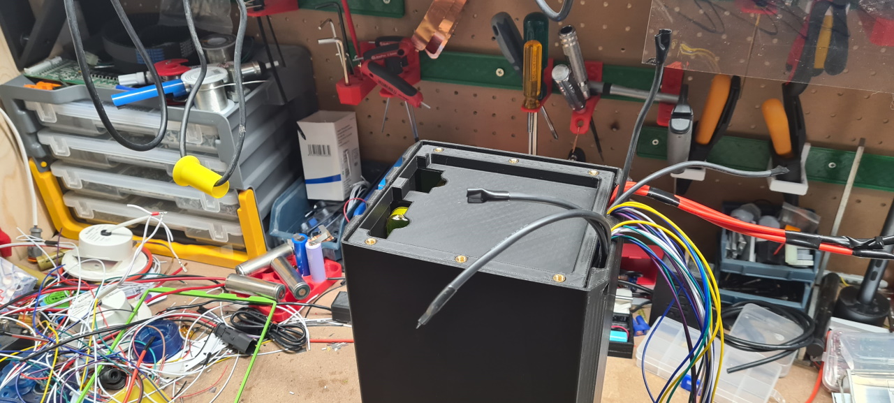
I’ve made the pack in such a way that there’s a SuperSoco connector connected to the 60A BMS and I’ve got 2 XT90 connectors that bypasses the BMS so that I can use the same pack on my future LightningRods BB builds..
The problem is that the SuperSoco uses a serial connection to talk to the battery to display the correct charge state and such which makes this pack show 5% charge even when fully charged.. I’ve ordered a connector that should solve that problem, still waiting to test it.
So.. since I didn’t rest enough after the head injury it kind of never got better. I’ve now been diagnosed with ‘fatigue’, when the brain kind of gets overloaded way too easily. This can happen after a serious head trauma I’ve been told, so I need to let the brain rest A LOT for some time to come. This totally sucks. I have not been able to ride my bike this summer as my brain has not been able to keep up with offroad riding..
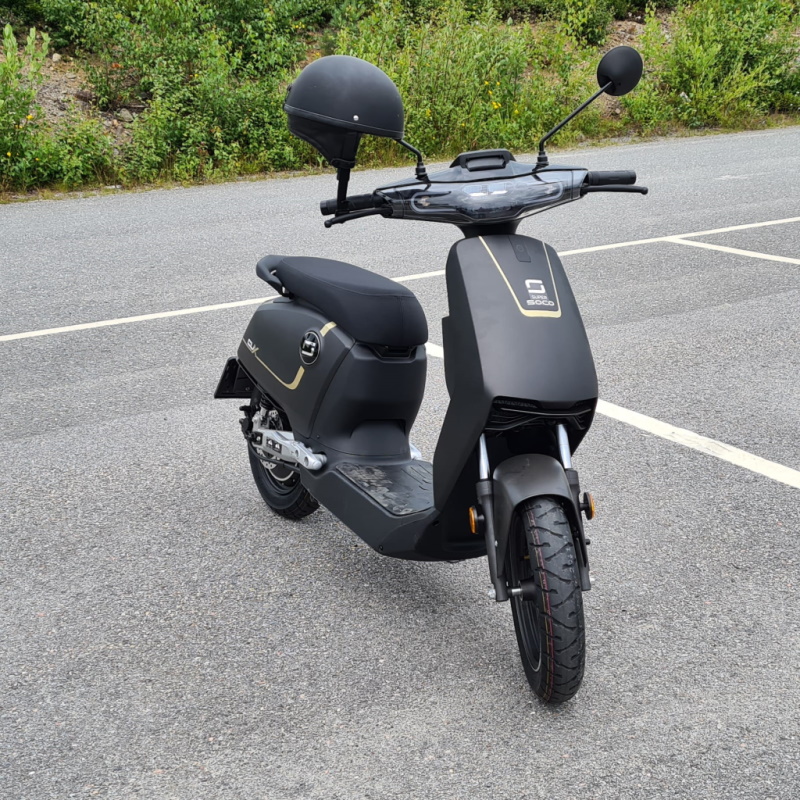
In order to be able to get some 2-wheel action me and my wife got one of these each.. not as quick or agile as the Swoop, but it’s super cozy and quite fun to glide around on!
So, it’s been quite a boring summer due to me not wearing a helmet and having a bit of bad luck.. So, if you’re reading this – take it from me.. wearing a helmet when riding is a super good idea, like EVERY time!
Keep safe – have fun. I’ll soon have more fun projects to share!
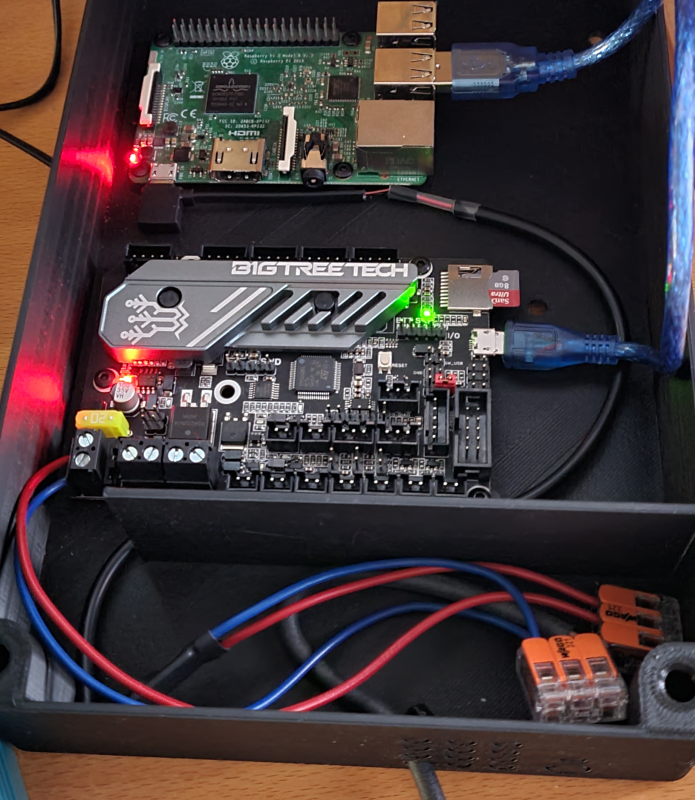
So, at first I finished building the CNC plasma by adding all the electronics and controllers..
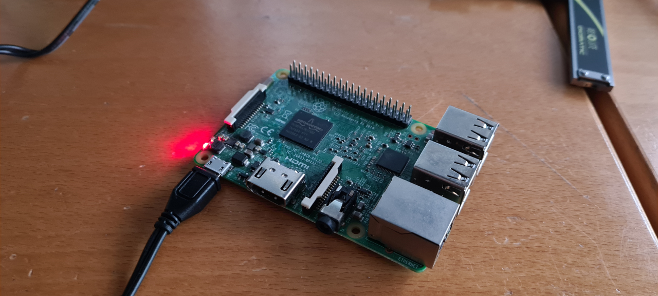
I printed a box for the controller and raspberry pi, added all the cables, a relay for the plasma trigger and closed it all off.
I had to do some work with Klipper to get it to work for the plasma cutter. It’s designed for driving 3D printers and making a config that works the way I wanted to was a bit tricky, but as I suspected it was totally possible.
So, after configuring Klipper and writing a custom POST processor for Fusion 360 it was finally time for the first cut..
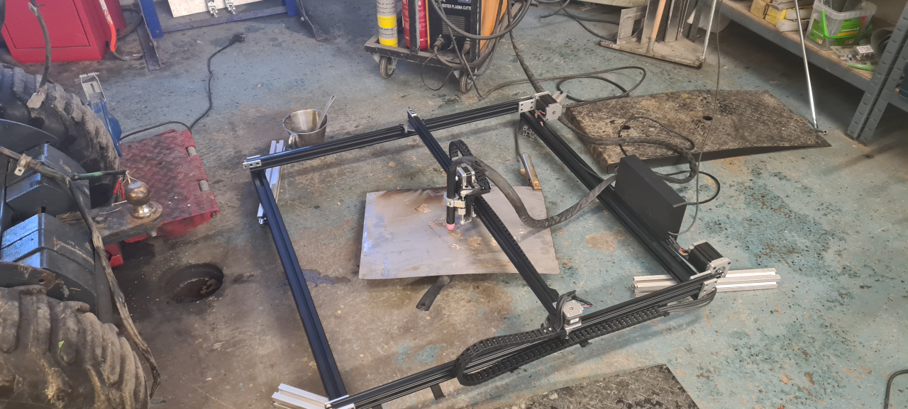
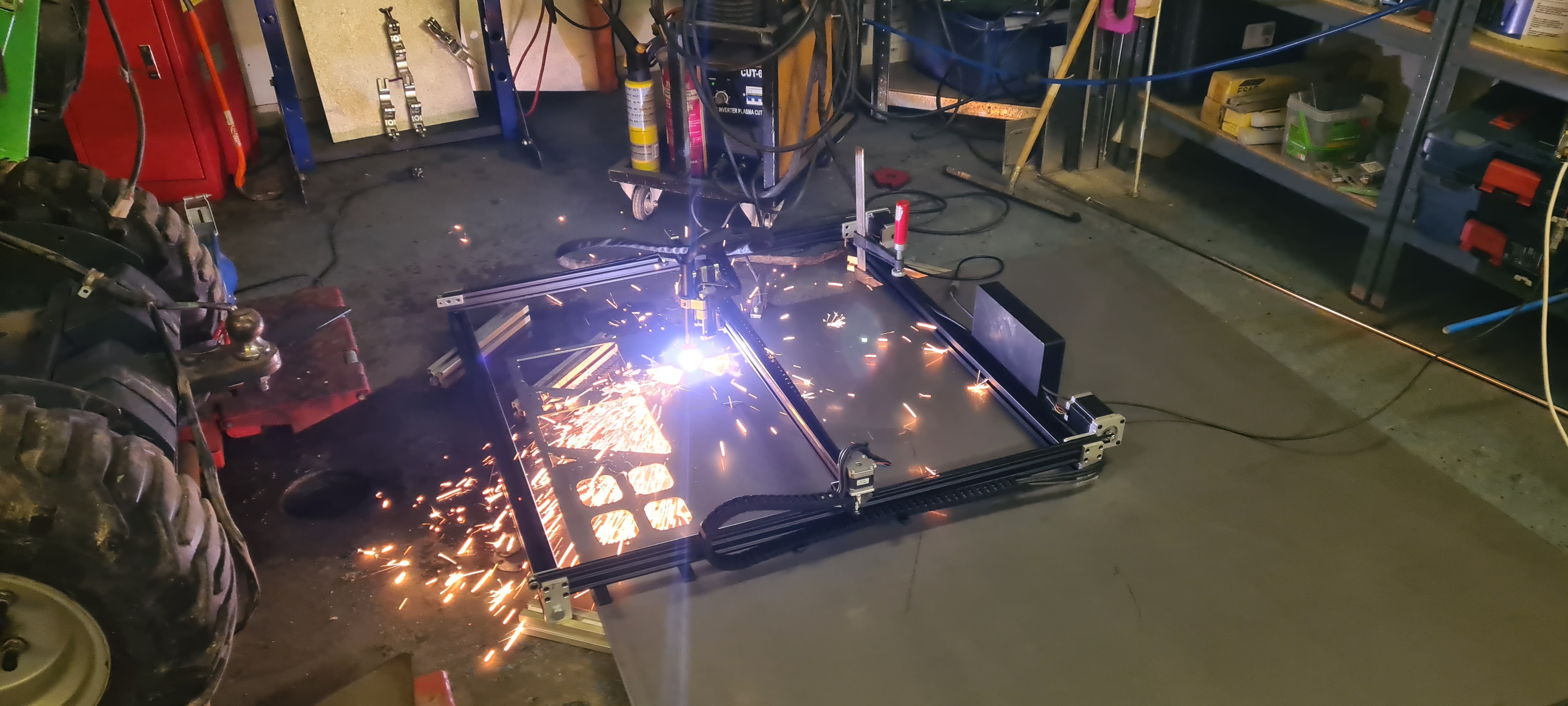
I placed the CNC plasma on 4040 profiles to get it off the floor, filled a frying pan with water and put a sheet of 1.5mm stainless on the pan.. and off we go!
It actually worked surprisingly well!
Without tweaking it actually cuts pretty cleanly but there is much room for improvement! So, time to put the plasma to work!
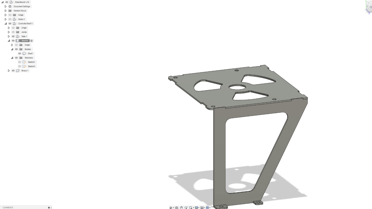
I made a shelf for the motor controller for the Evant in CAD, did a quick CAM processing increasing the feed to 2000mm/min and uploaded it to the plasma.
And of course, when I took the video the controller failed. I did some more runs and it seems the X stepper controller has a tendency to reset every now and then.. And then I realised I’m using a 60W 12V PSU.. That means I’ve got a total of 5A to run all the steppers, the controller and the pi.. which was a bit too little. After switching to a 200W PSU everything worked fine!
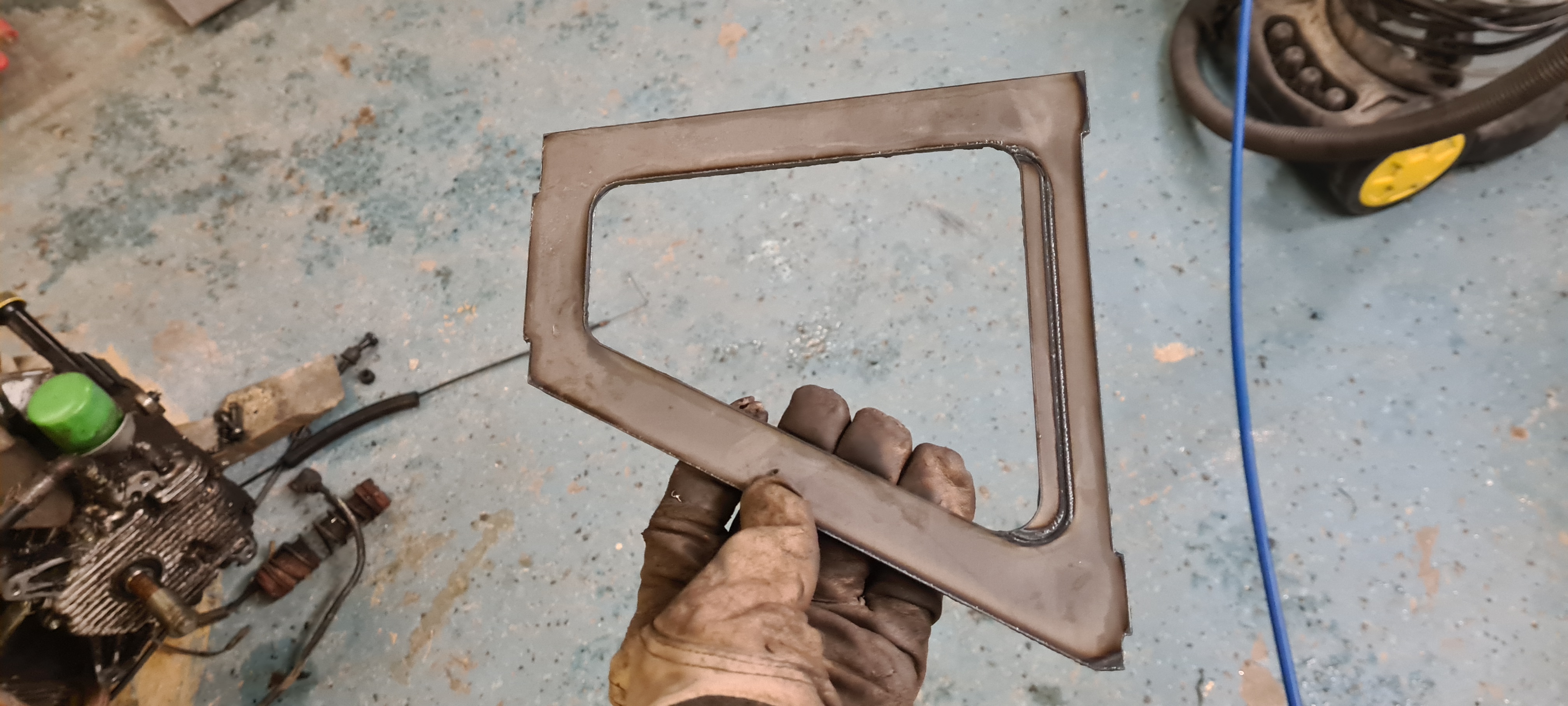
I made two side walls..
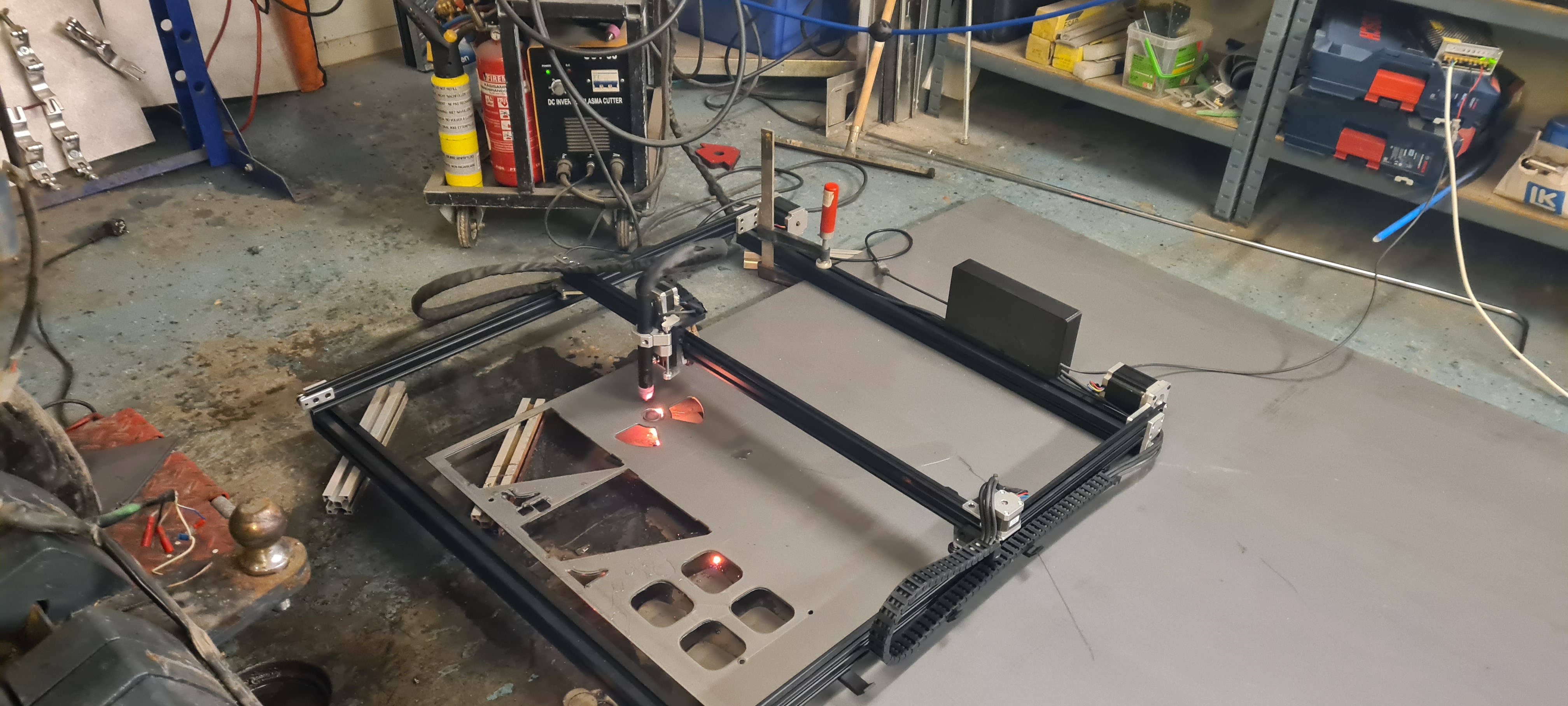
And of course when it’s CNC controlled there’s room for.. well.. flare. 🙂
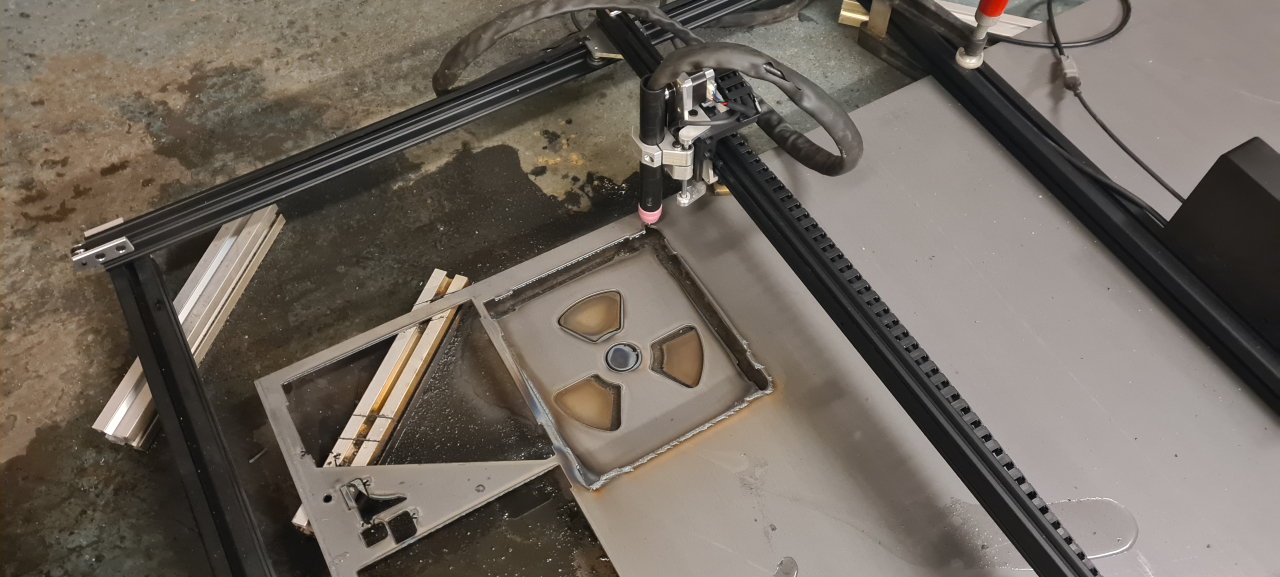
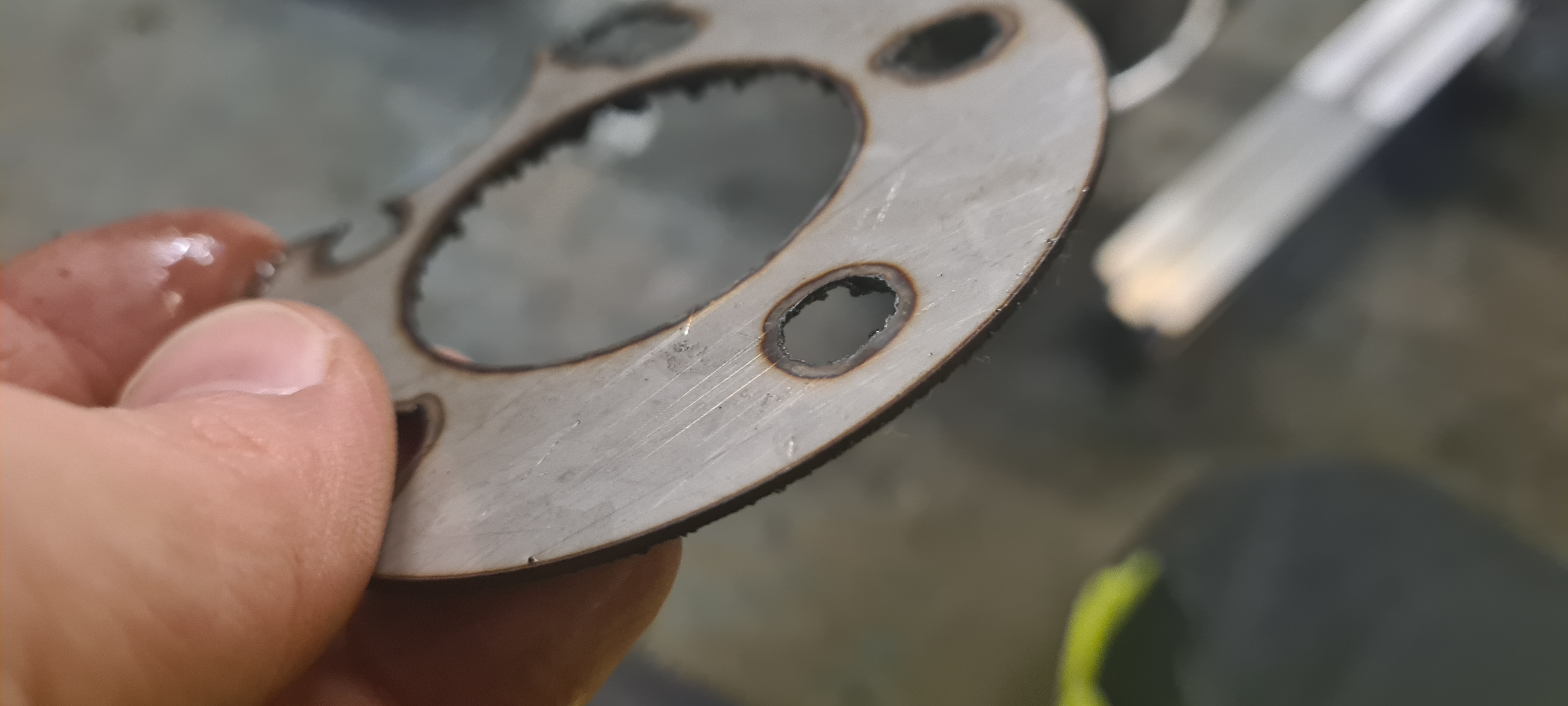
After tweaking the feed and amps of the plasma I’ve got it to where the cut parts fall off the metal sheet. Sure, there’s room for improvement as I get quite a buildup of steel on the back of the part but a quick runover with the grinder solves that.
I just had to tack weld the parts together to see how well it fits.
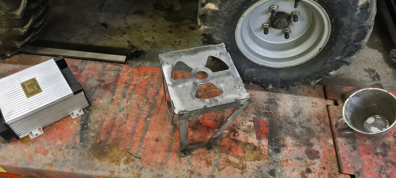
It’s not as precise as the mill but MUCH faster, and cuts 3mm steel sheet in seconds!
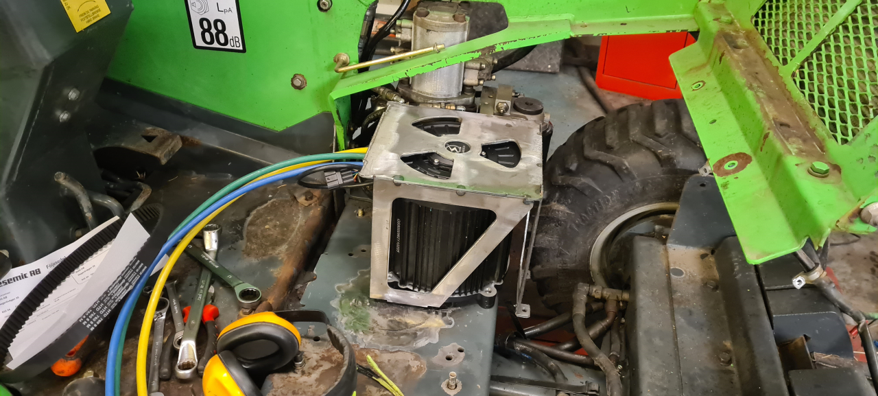
I’m going to turn the motor 180 degrees to get the cables poking out the back and the controller shelf is going to be turned 90 degrees to mount at the left and front sides of the motor.
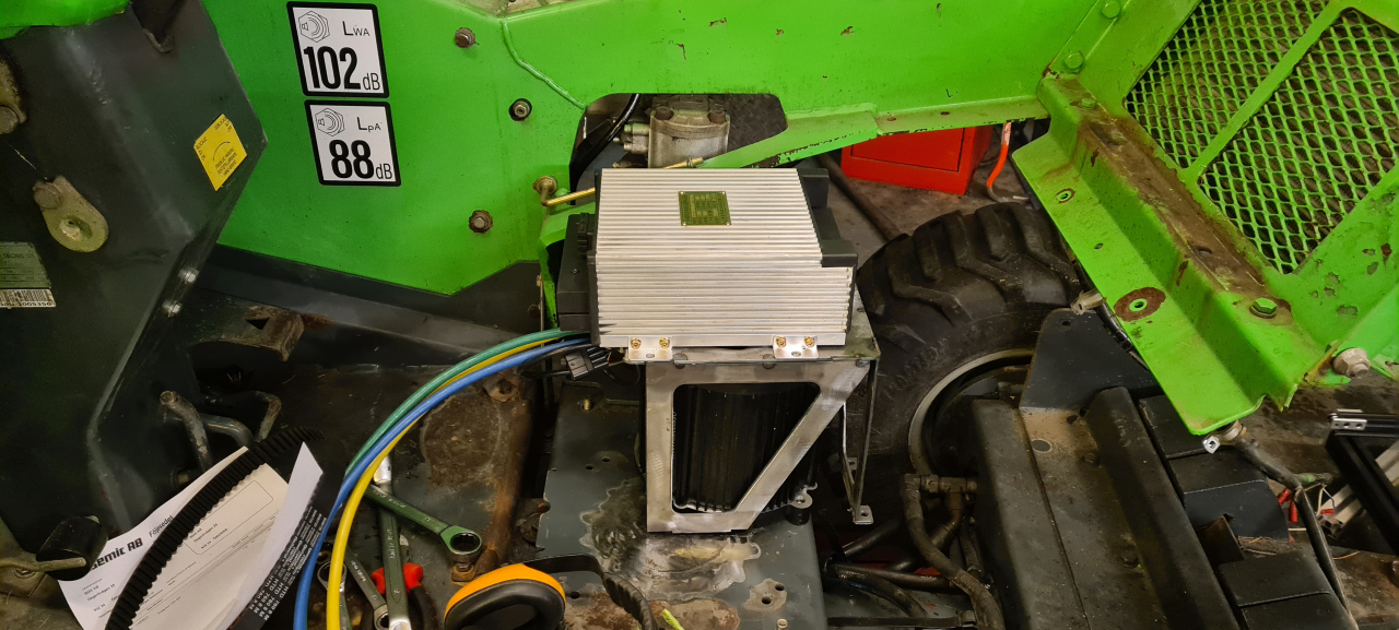
Something like this..
We’re getting closer to testing the Evant. Today I got the new belt which I hope will fit the new pulley and motor location.. But this weekend I’m going to focus on building the kitchen so we’ll see how far I get with the Evant. Considering the snowfall here the past week or so it’d be really good to get it running soon..
TBC