So, since recovery from the fatigue syndrome is super slow so will updates on the project be. That’s just due to most of my afternoons being spent resting and trying to get the brain to recover. But some progress has been made lately, both recovery- and project wise.
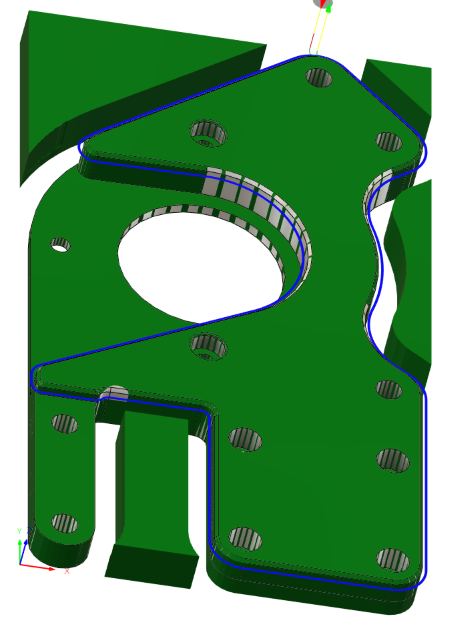
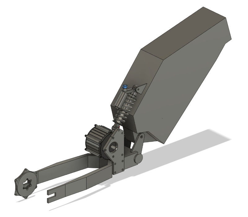
I’ve iterated the motor mounting plate design a bunch of versions and am pretty happy with it. Time to make some proper parts.
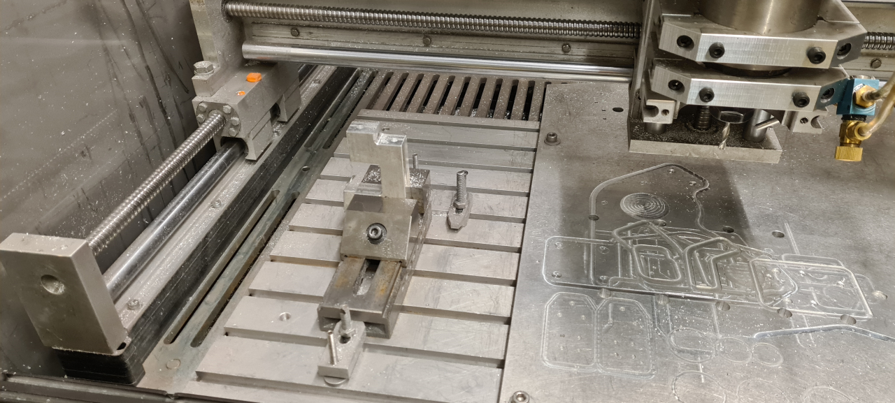
After some CAM-work in Fusion360 I cut some sheet aluminium and got to milling.
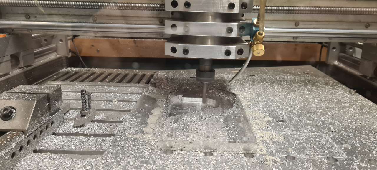
The mill really makes a mess throwing shavings everywhere, but since I built the enclosure at least it doesn’t fill the entire workshop with metal shavings. 🙂
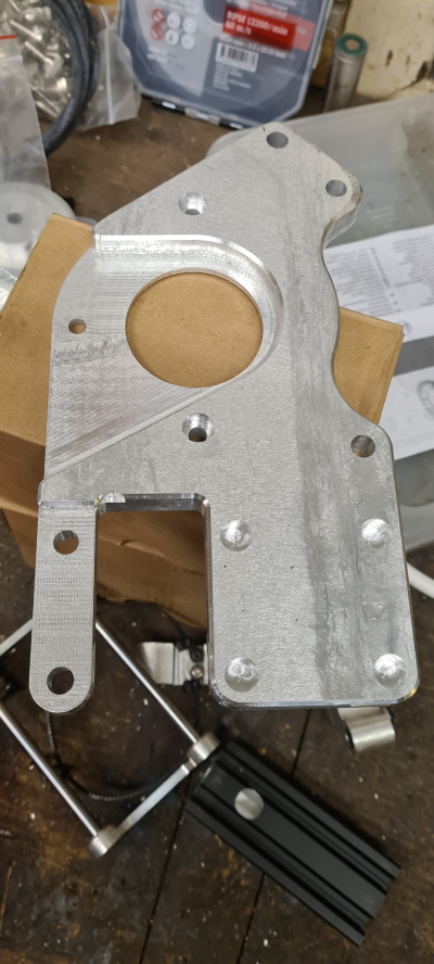
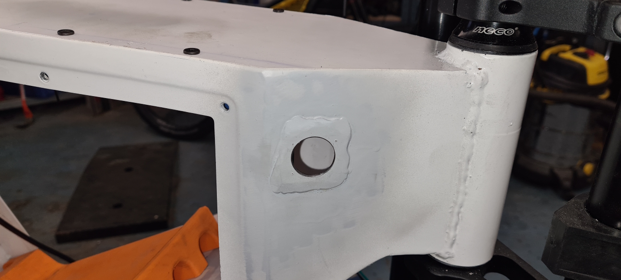
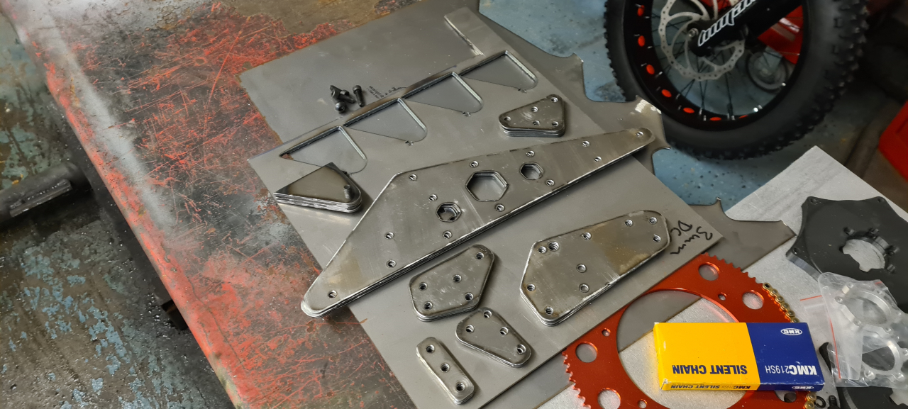
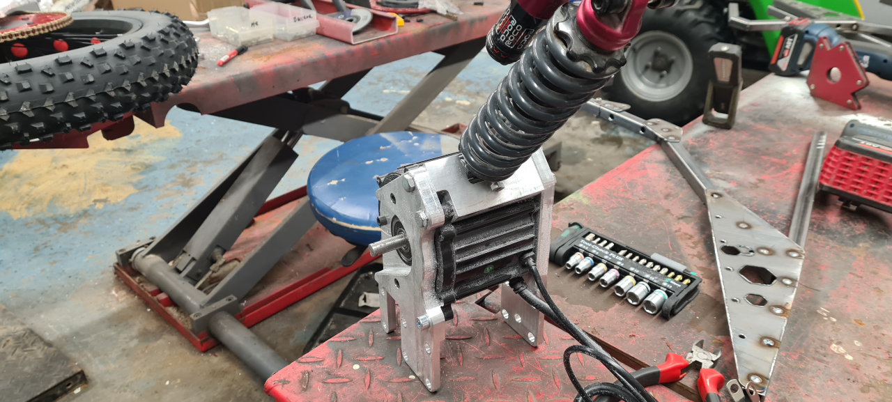
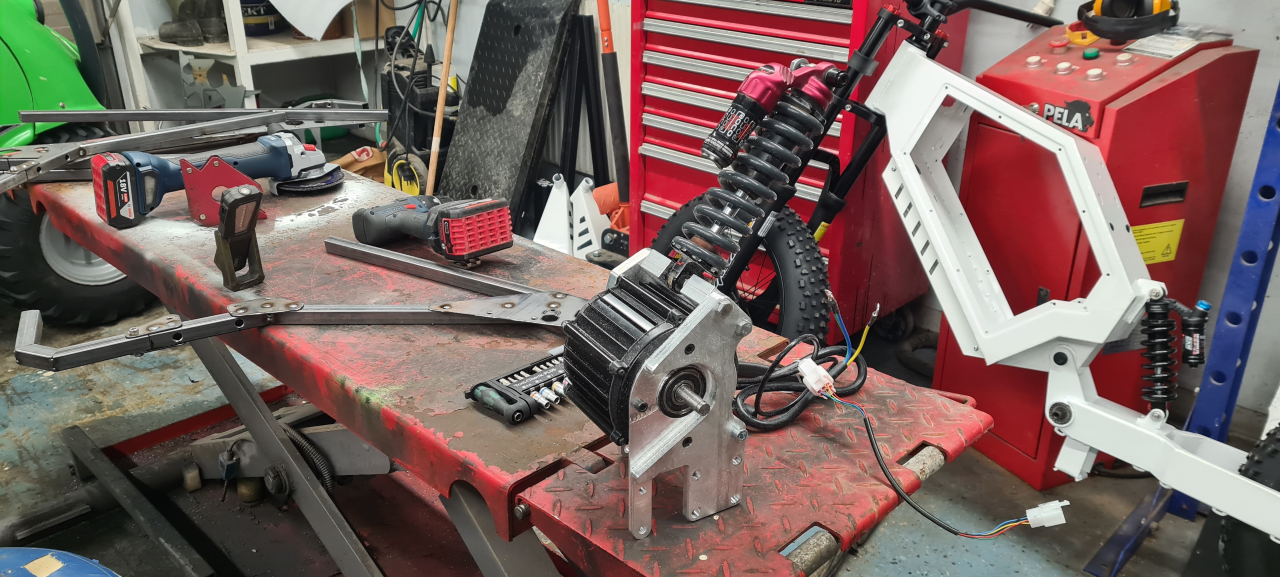
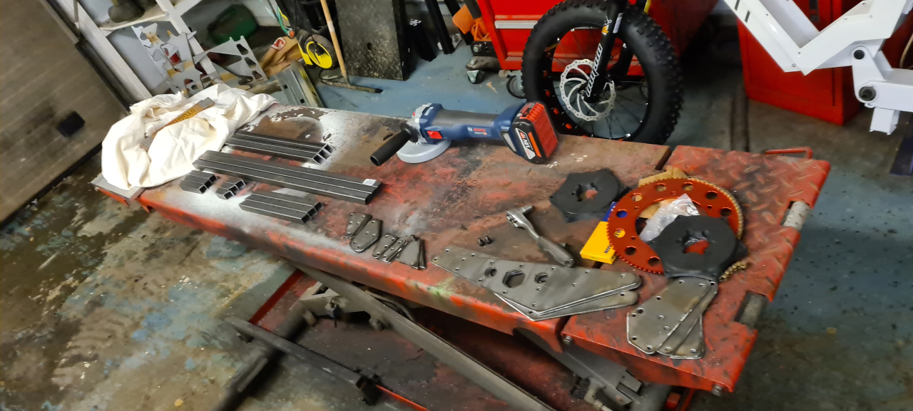
The result when milling aluminium is pretty amazing. This part looks even better IRL than in the pictures and being made from 13mm thick plate it’s super sturdy!
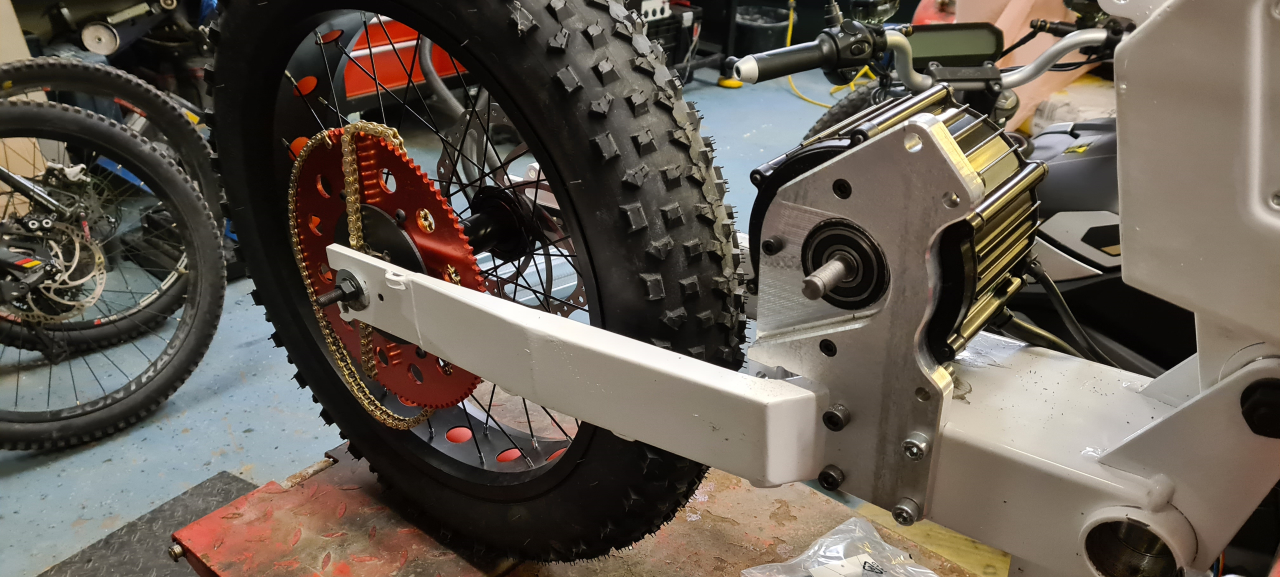
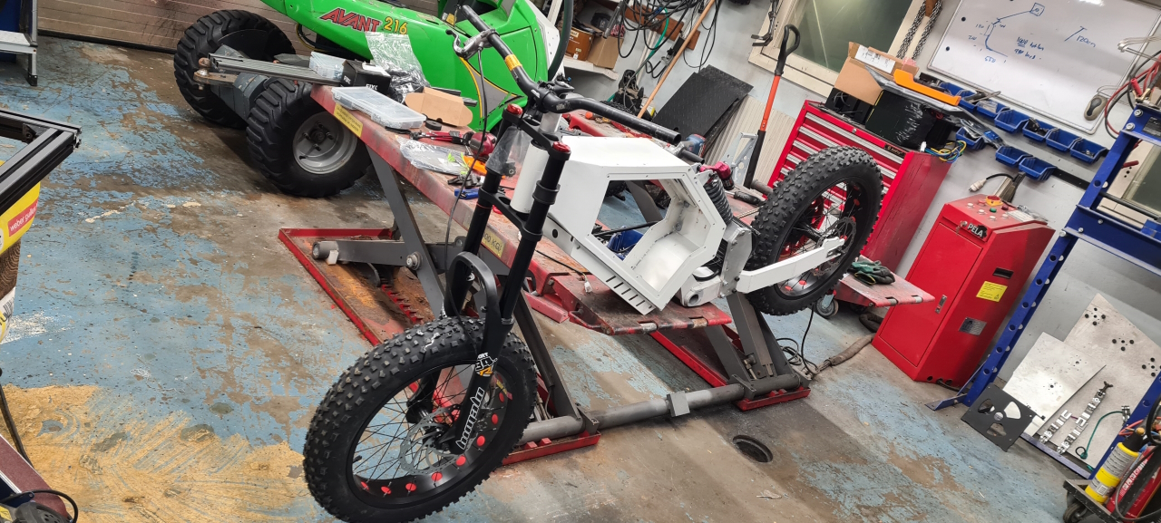
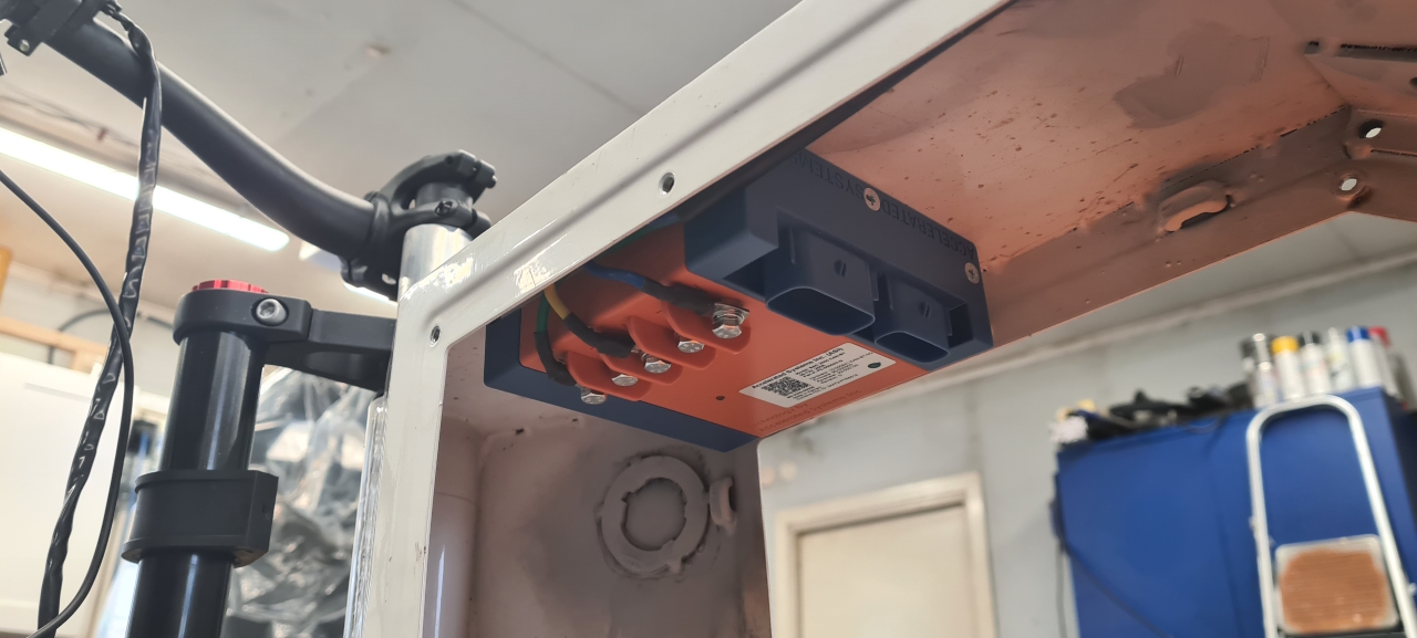
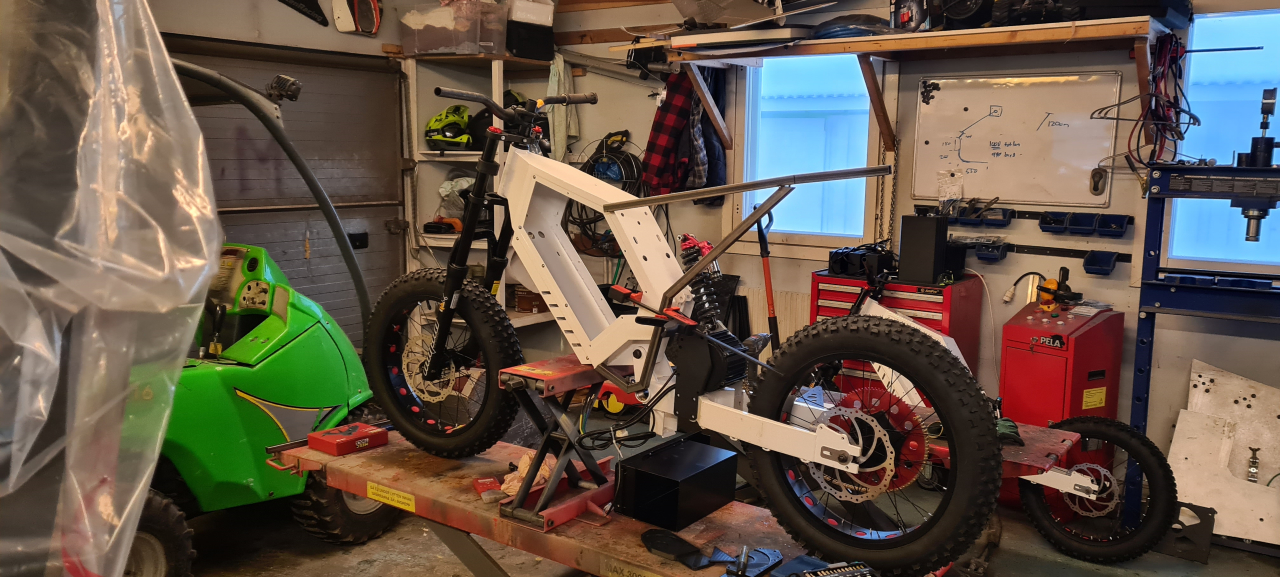
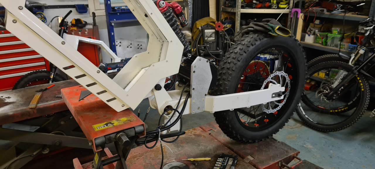
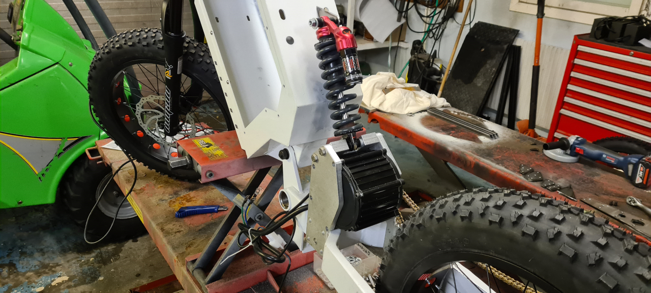
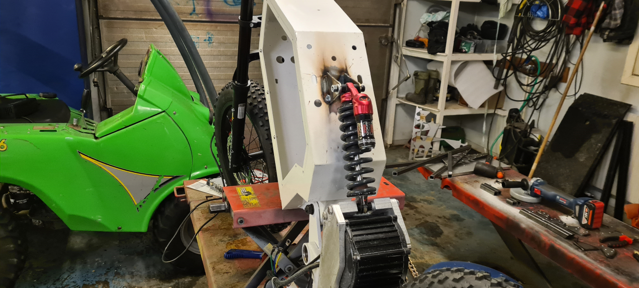
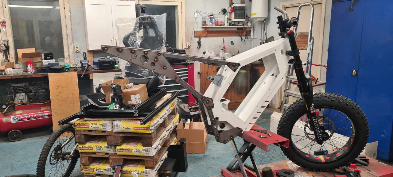
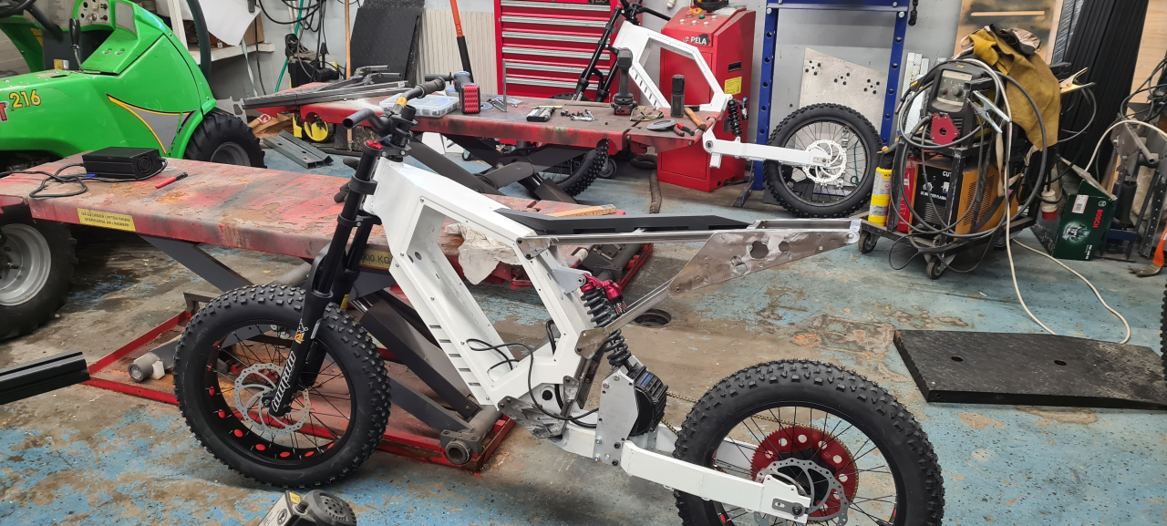
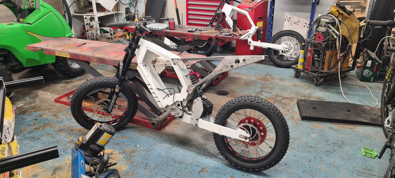
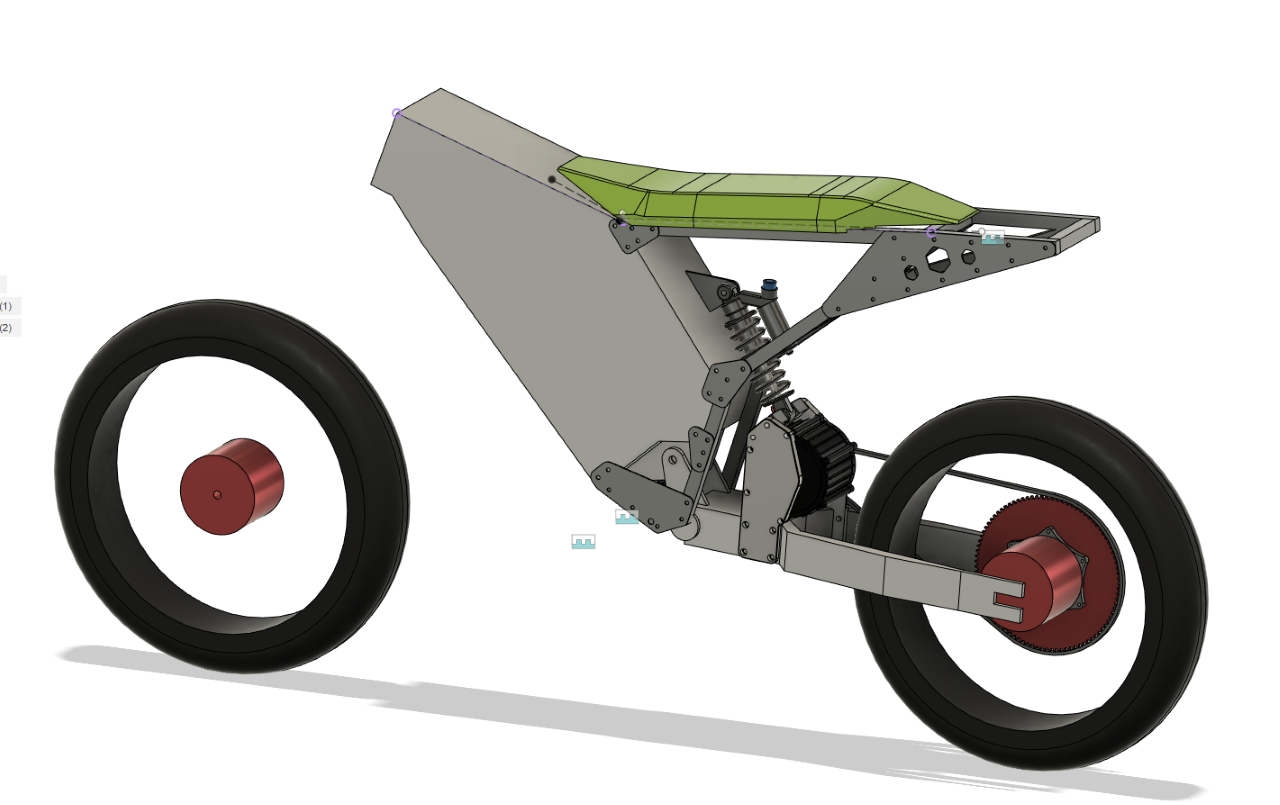
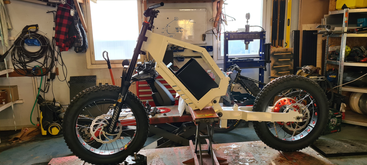
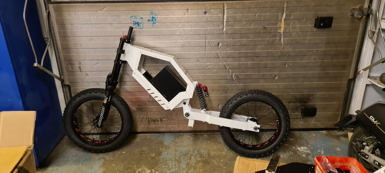
Bolting it down to the frame and mounting the motor everything fits super snugly and I’m starting to question the decision to make a mounting plate on the rear side of the motor too since the motor seems rock solid as it sits now. Buuut, it’s better to make it to tough so we’ll make one just for the fun of it.
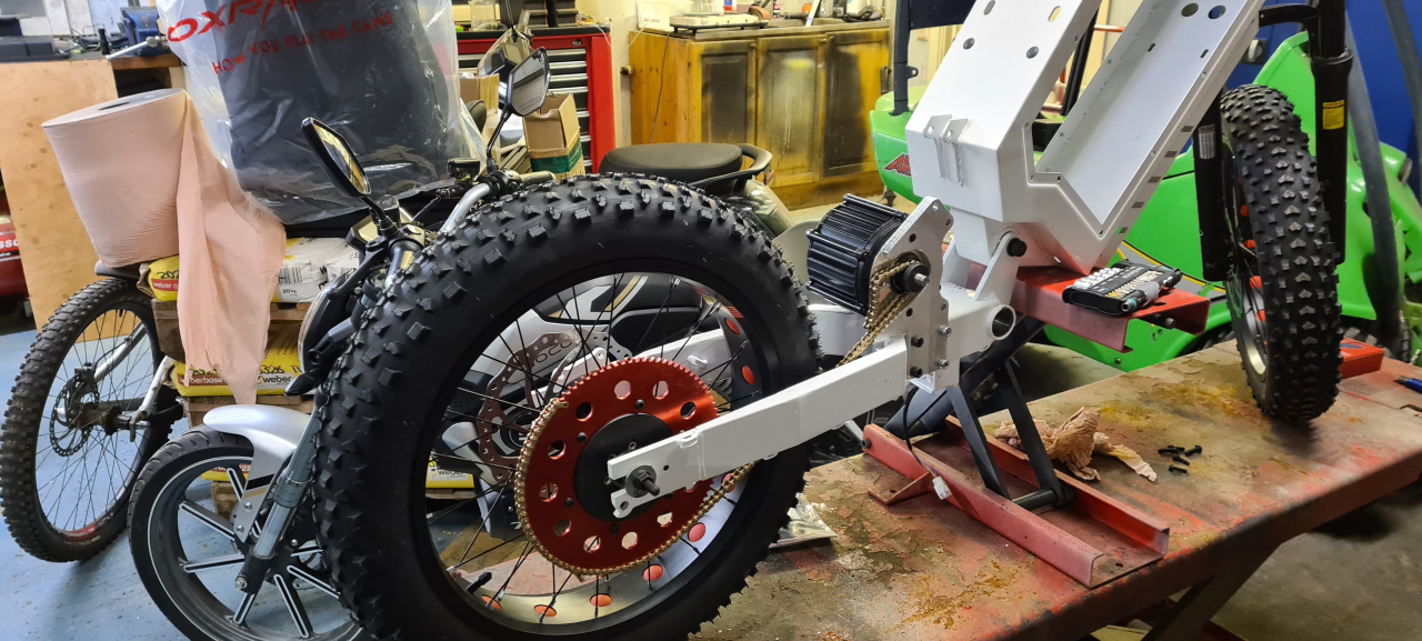
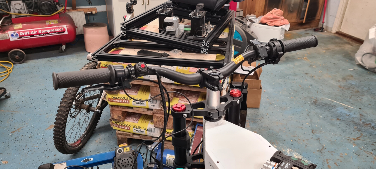
Test fitting the chain again with the proper motor mount. I’ll have to make one last prototype of the rear sprocket adapter but now I get proper clearance to both the wheel and the frame so the next adapter is just to get the chainline straight. Right now I’ve got the largest sprocket I’ll use mounted to make sure the chain doesn’t strike the frame in the worst case scenario.
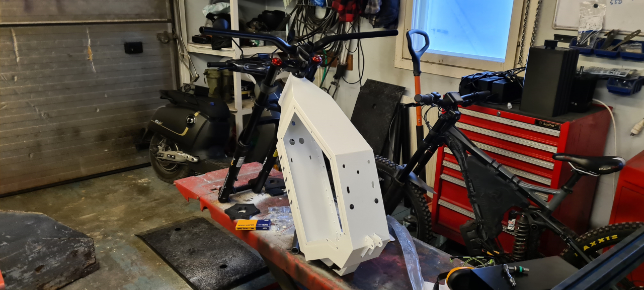
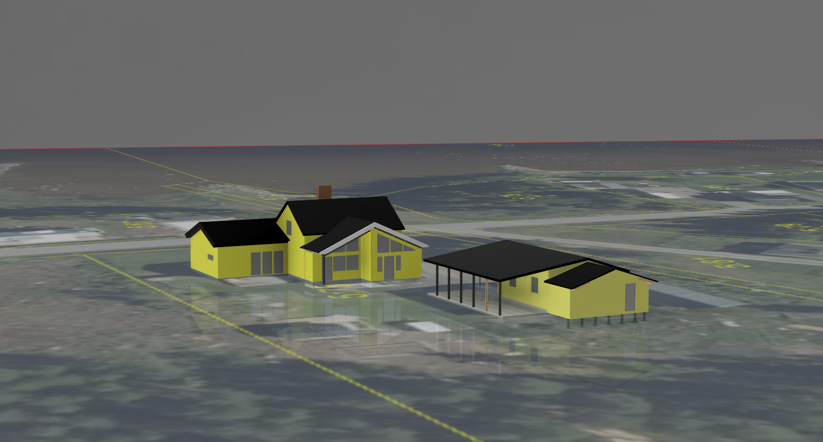
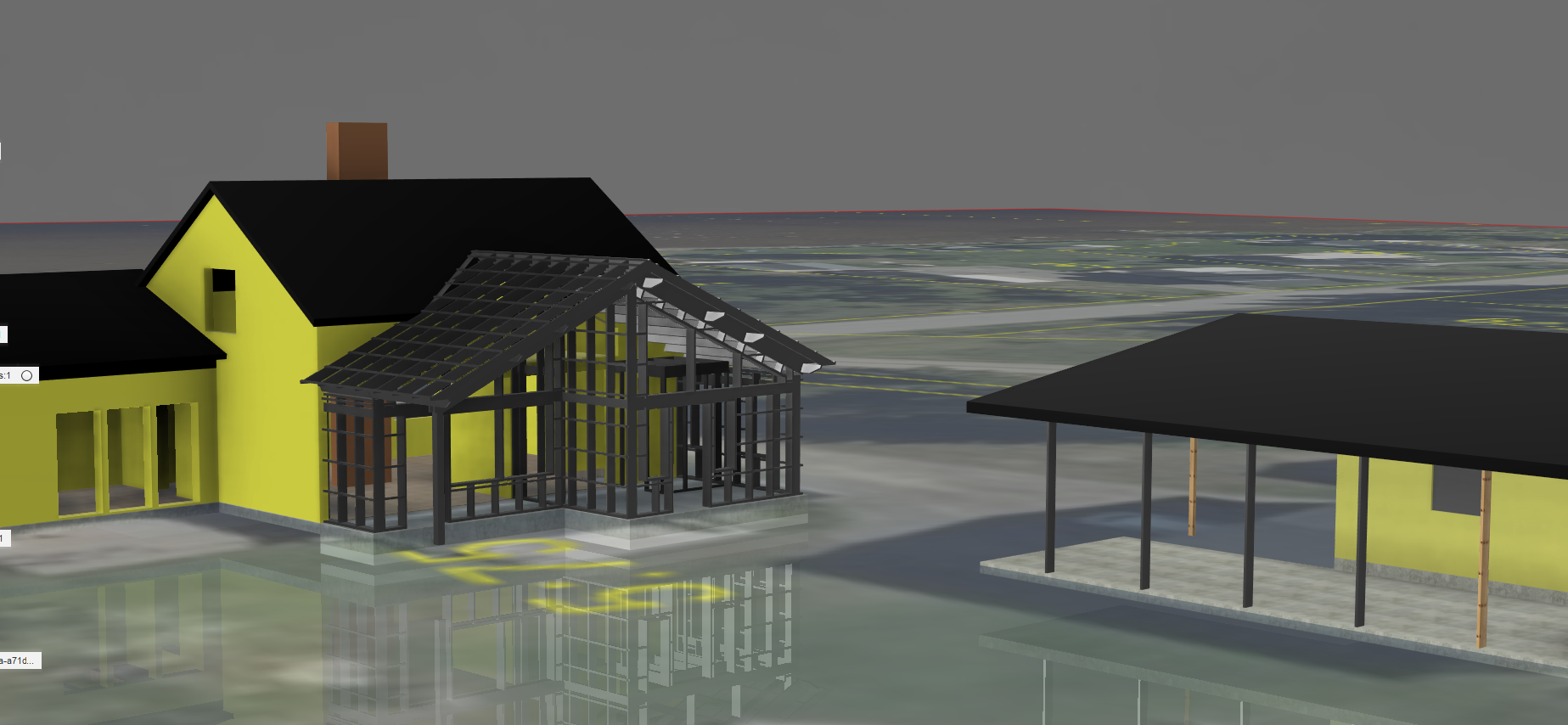
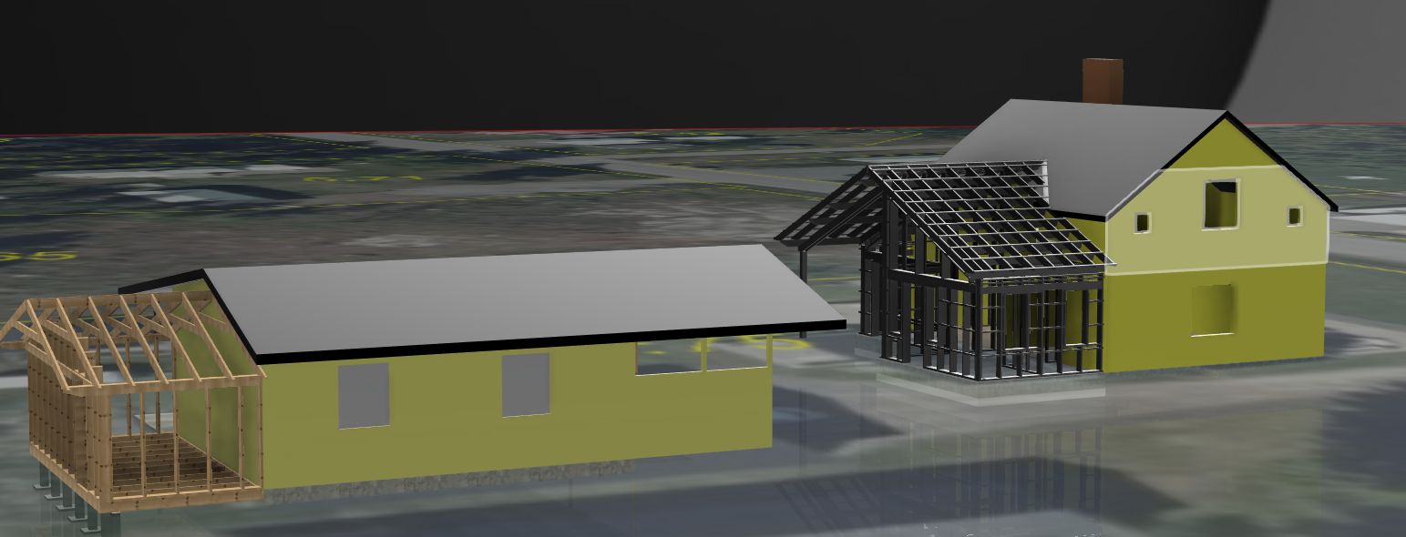
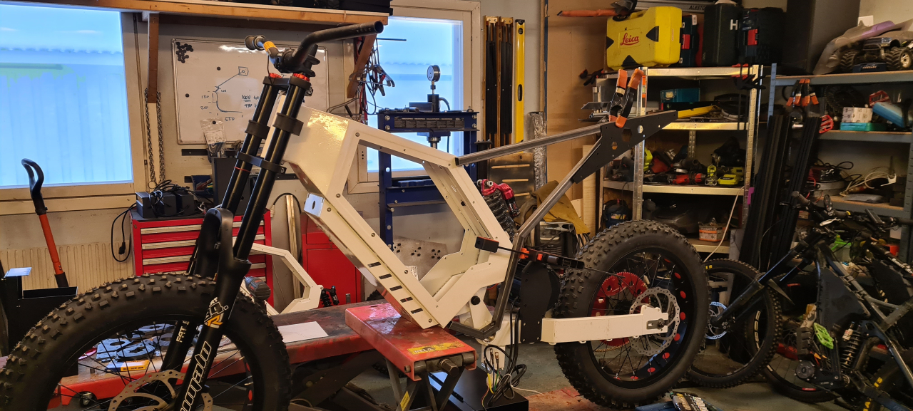
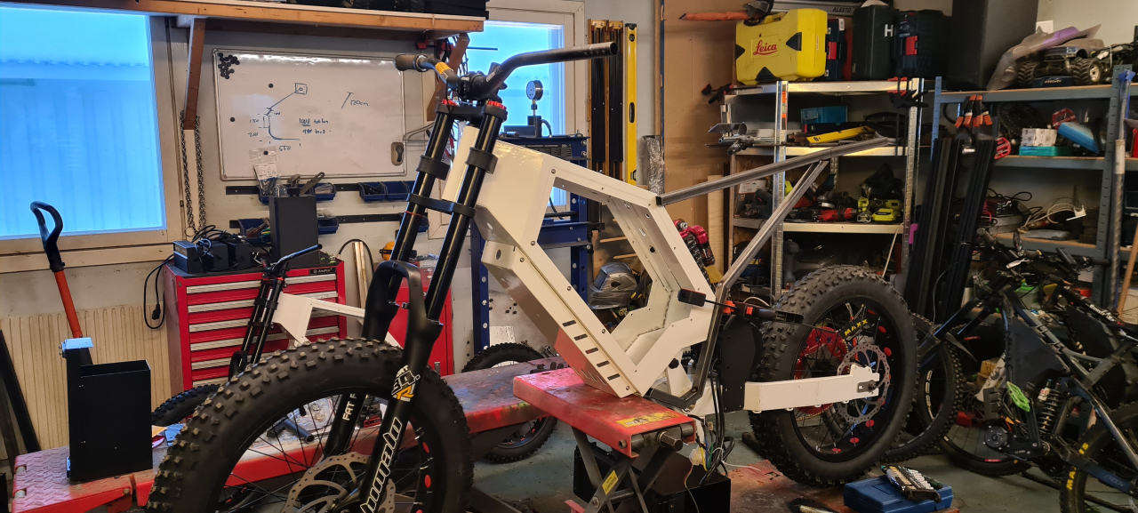
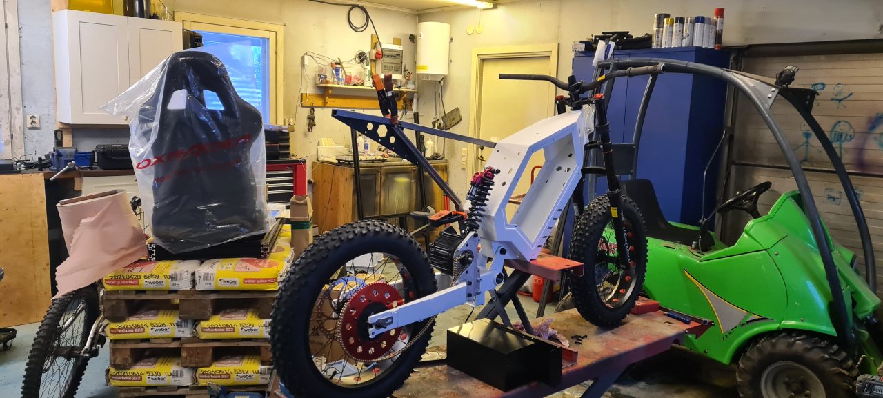
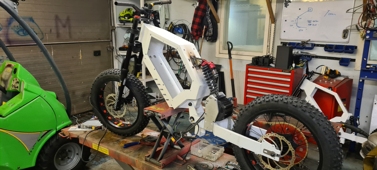
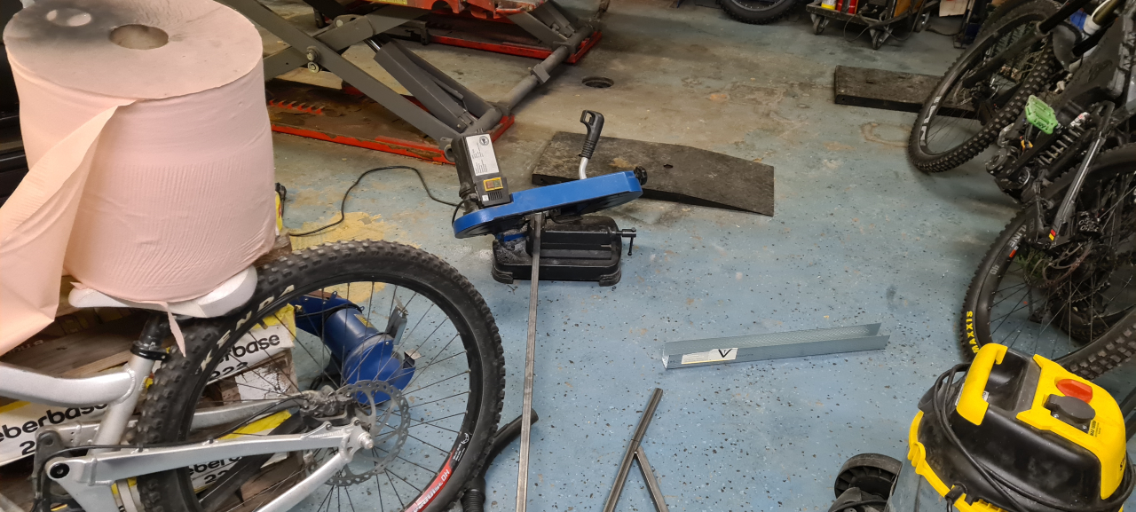
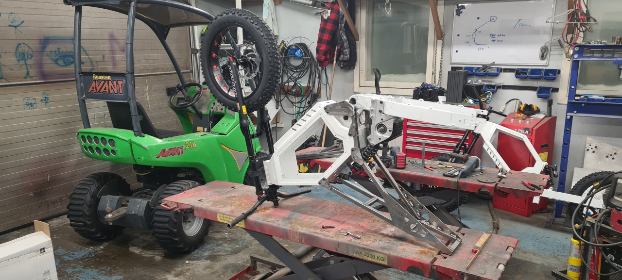
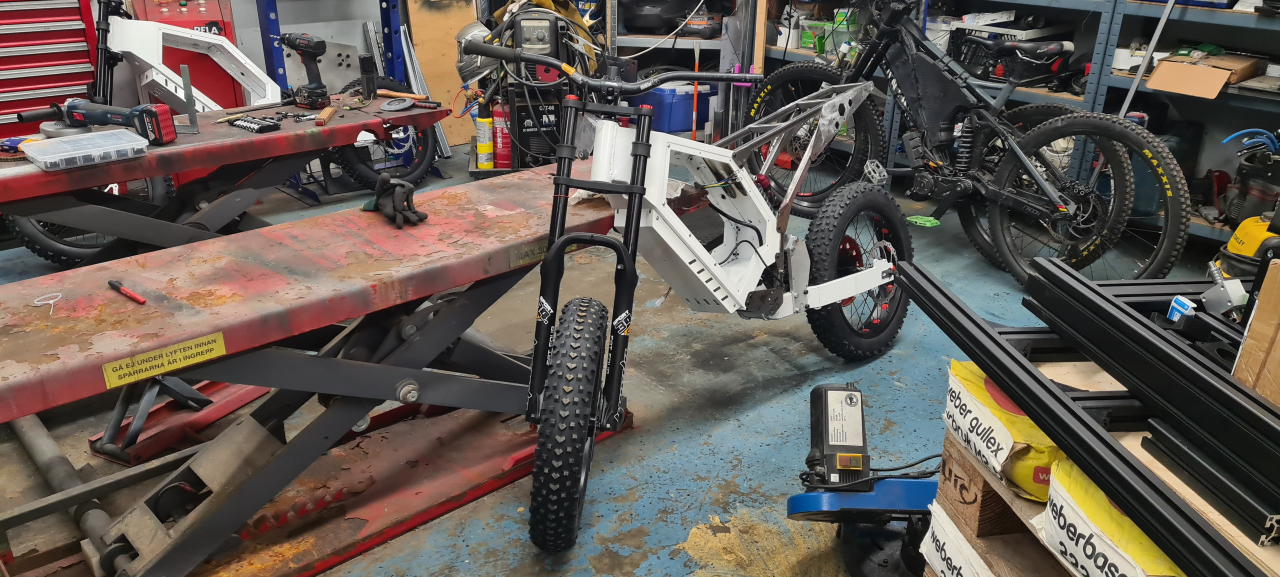
I’ve been getting parts for the second bike aswell. I’m going to build it up to use as a template for checking the geometry so as not to mess anything up when customizing the bike. It’s a chinese clone frame so the geometry probably isn’t perfect to begin with but it’s good to at least know what I’ve changed when re-designing it.

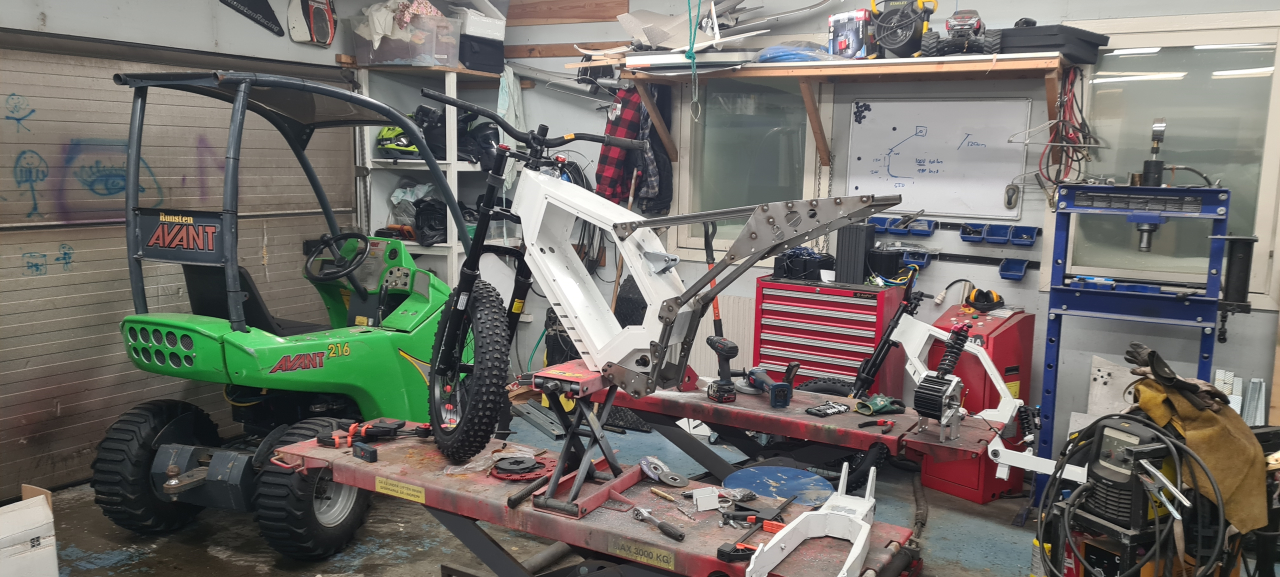
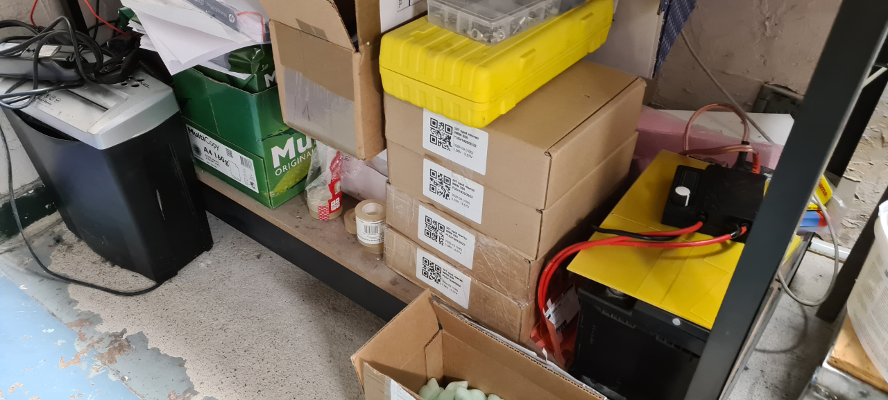
Winter is coming and right now the garage/workshop is a mess with all the projects and stuff that needs storing and protecting from the cold. It’s a bit annoying trying to get stuff done in there but it is what it is. I’ve got to move stuff out when using the plasma cutter that I need for the coming project of making a seat and upper shock mounts..
So, what’s next?
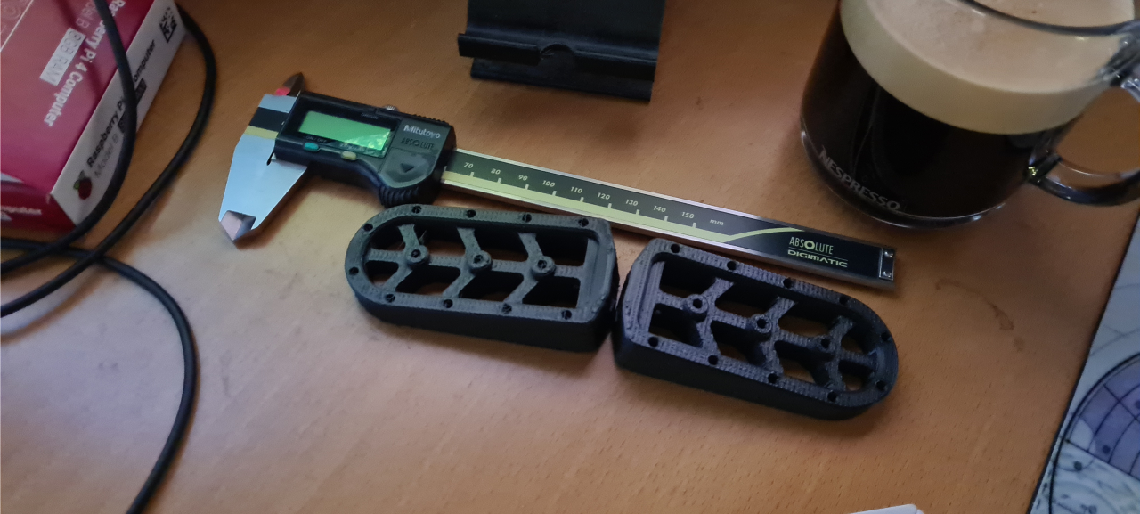
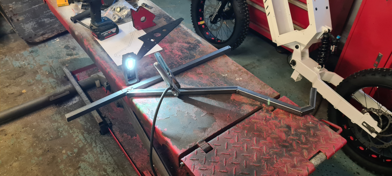
Since footpegs seem utterly expensive I’ve started mocking up custom footpegs for the bikes. I yet have not decided on how and where they should mount to the bike but I know I don’t want them sitting on the swing as the original pedals were mounted on the bomber frame.
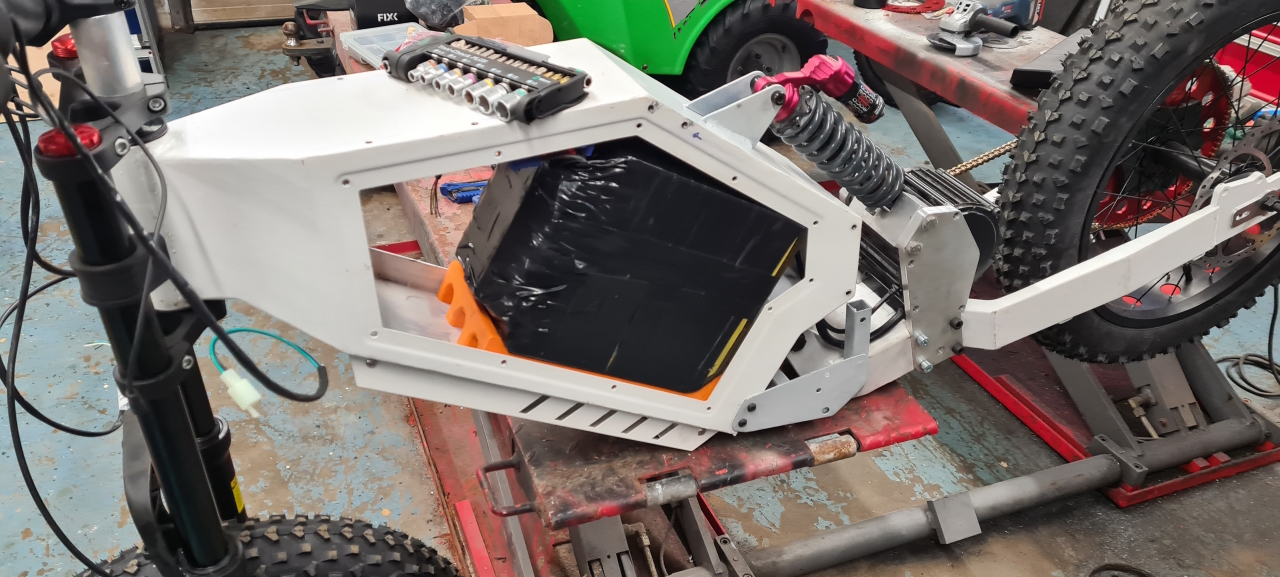
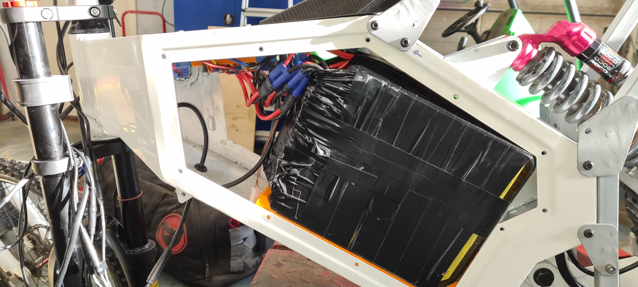
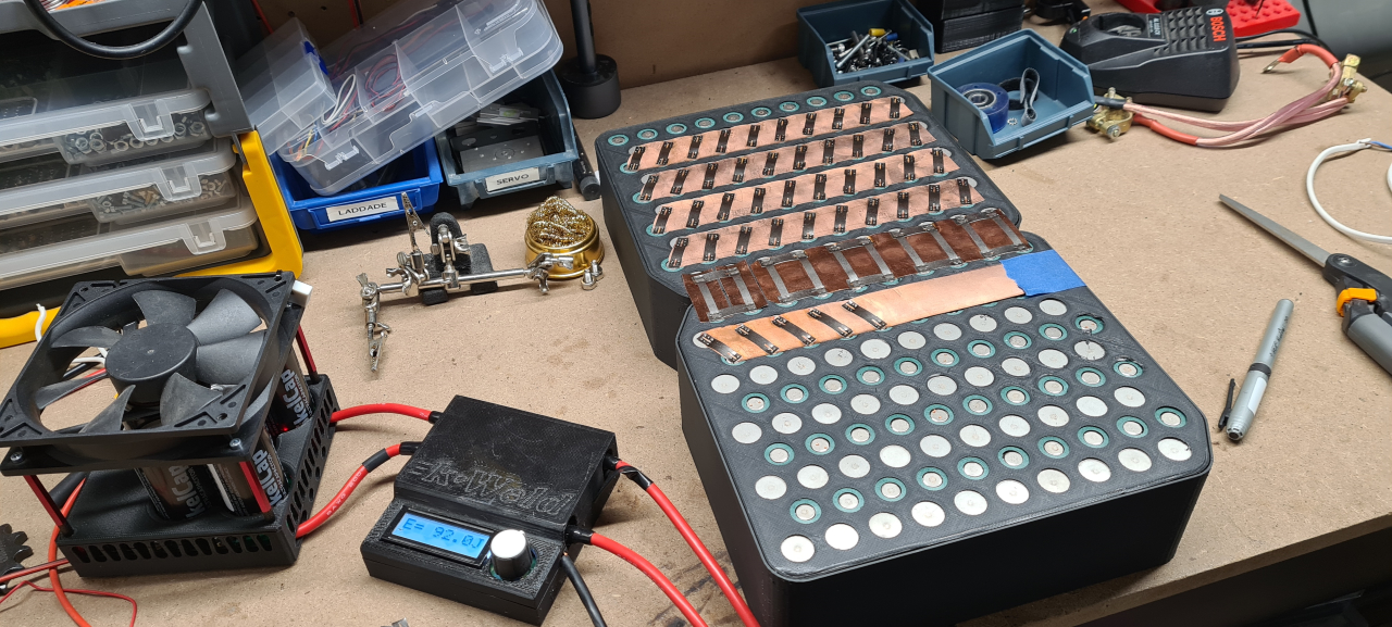
The 21700 cells have arrived so I’m looking at making the batteries for the bikes. It’s going to be a 20s10p pack made from Samsung 30T cells at 3000mAh and 35A.
For the first time ever the build is not restricted by the available space in the frame as the bomber box would fit a HUGE pack if filling it up. I’ve decided to go with 200 cells per pack due to cost and weight. This pack is going to be around 14kg just in cells so it’s going to be heavy enough as it is.
72v nominal at 30Ah yields about 2,2kWh which should let us have fun for at least 100km at a time I hope, of course depending on how we ride. =)
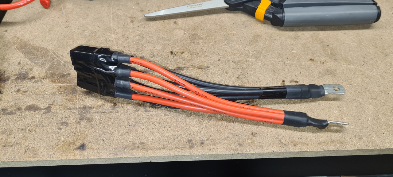
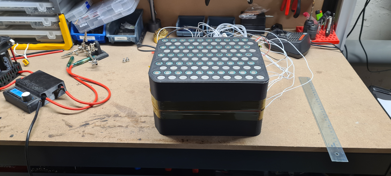
I’m using the same method of building the packs as I do on regular bike packs but as with the avant battery this is going to be a CU sandwich type pack as to be able to deliver 300A of peak current..
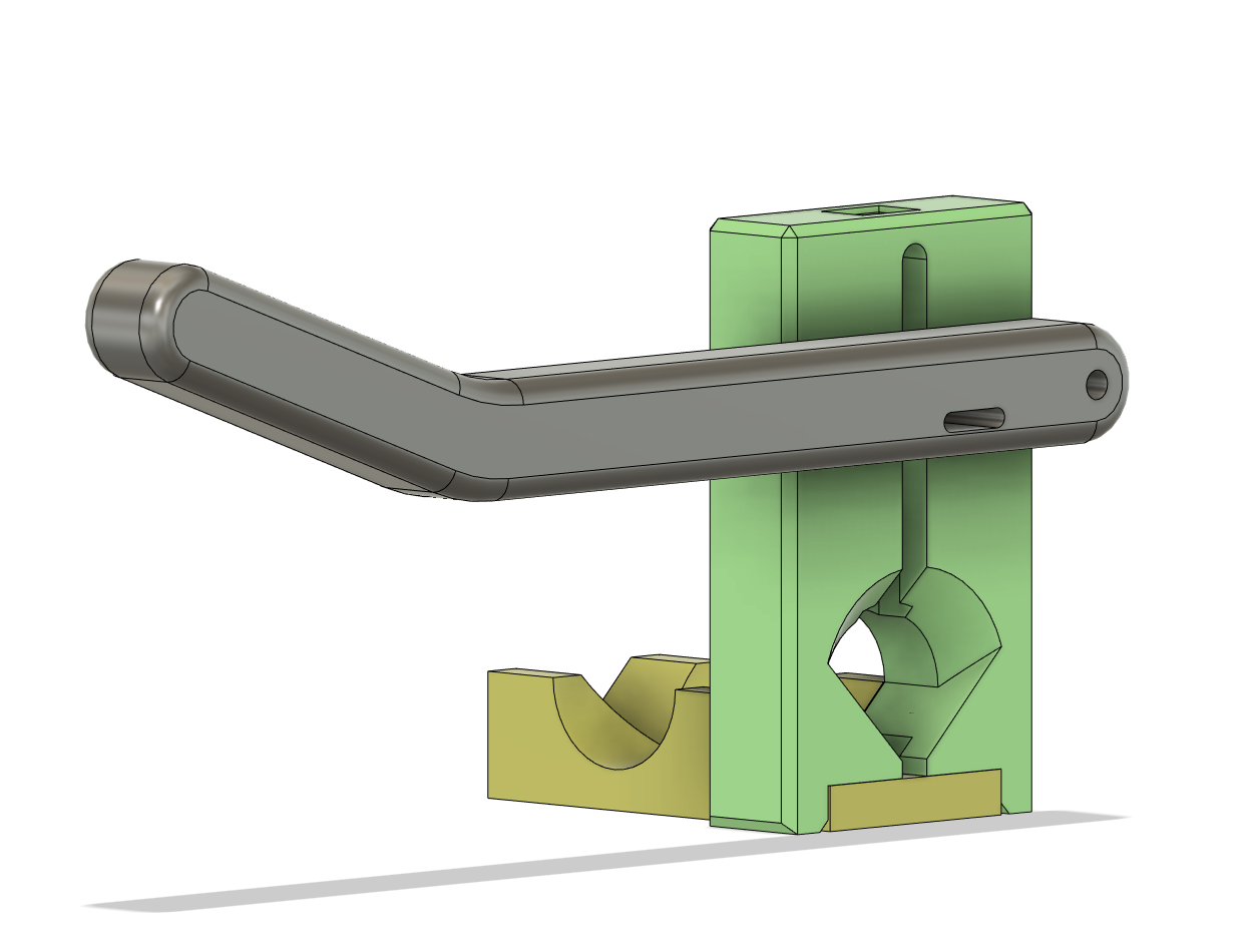
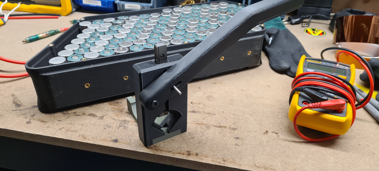
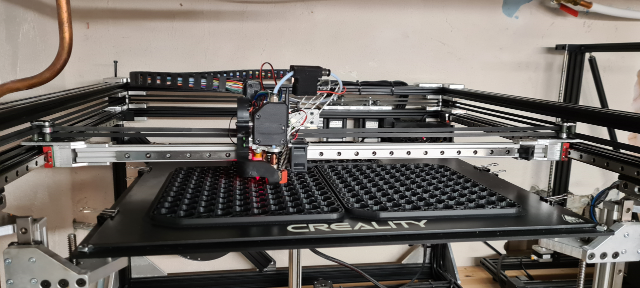
Here I’m printing the cell frames, three at a time, on my ”Stoorn v2”-printer. The next step in the battery process is making cell spacers, measuring the voltage on the cells and starting to put the cells into the pack before welding.
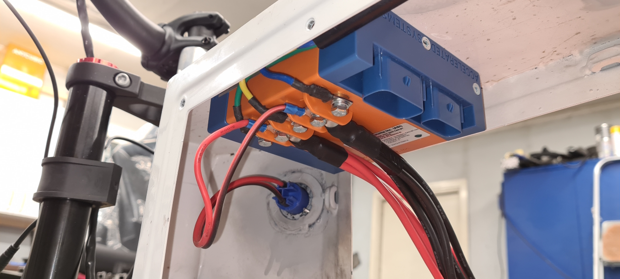
I’ve ordered a pair of ANT 300A BMSes as I’ve used them on all my avant packs and am super happy with the way they work. I’m looking at getting some 10A+ 72v battery chargers to charge the packs in a reasonable amount of time but we’ll see what we end up using.
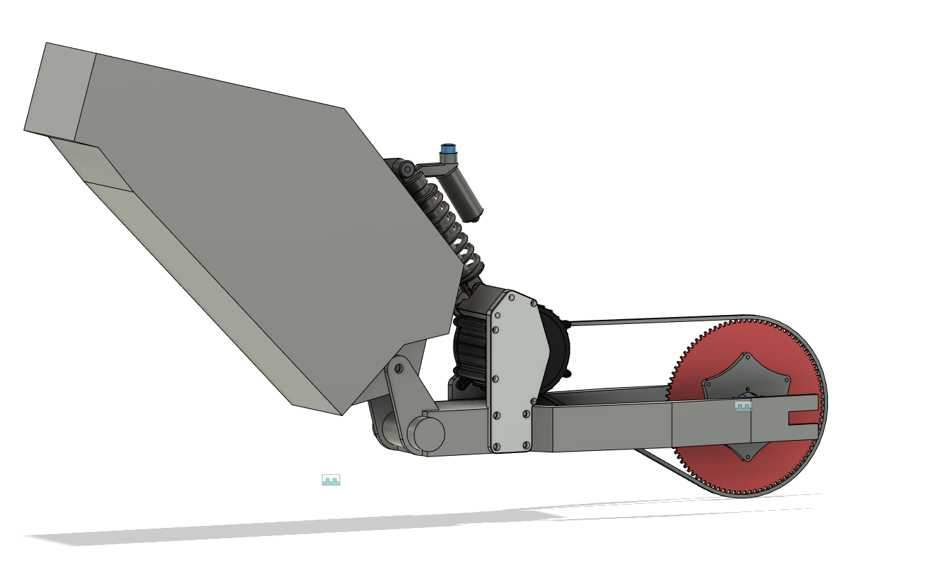
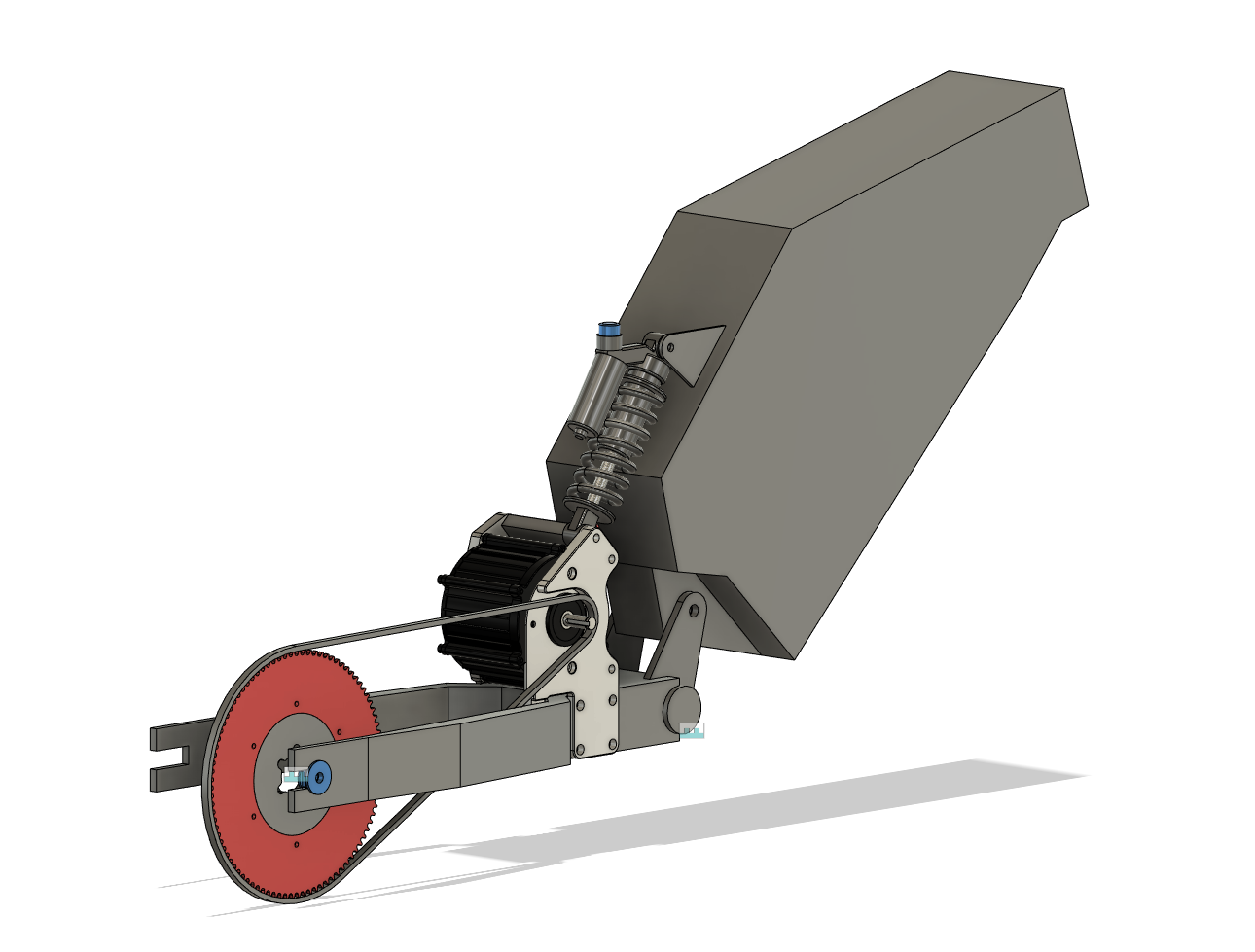
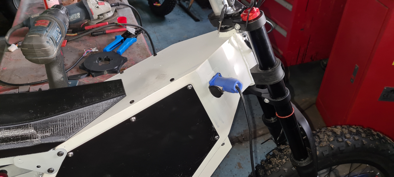
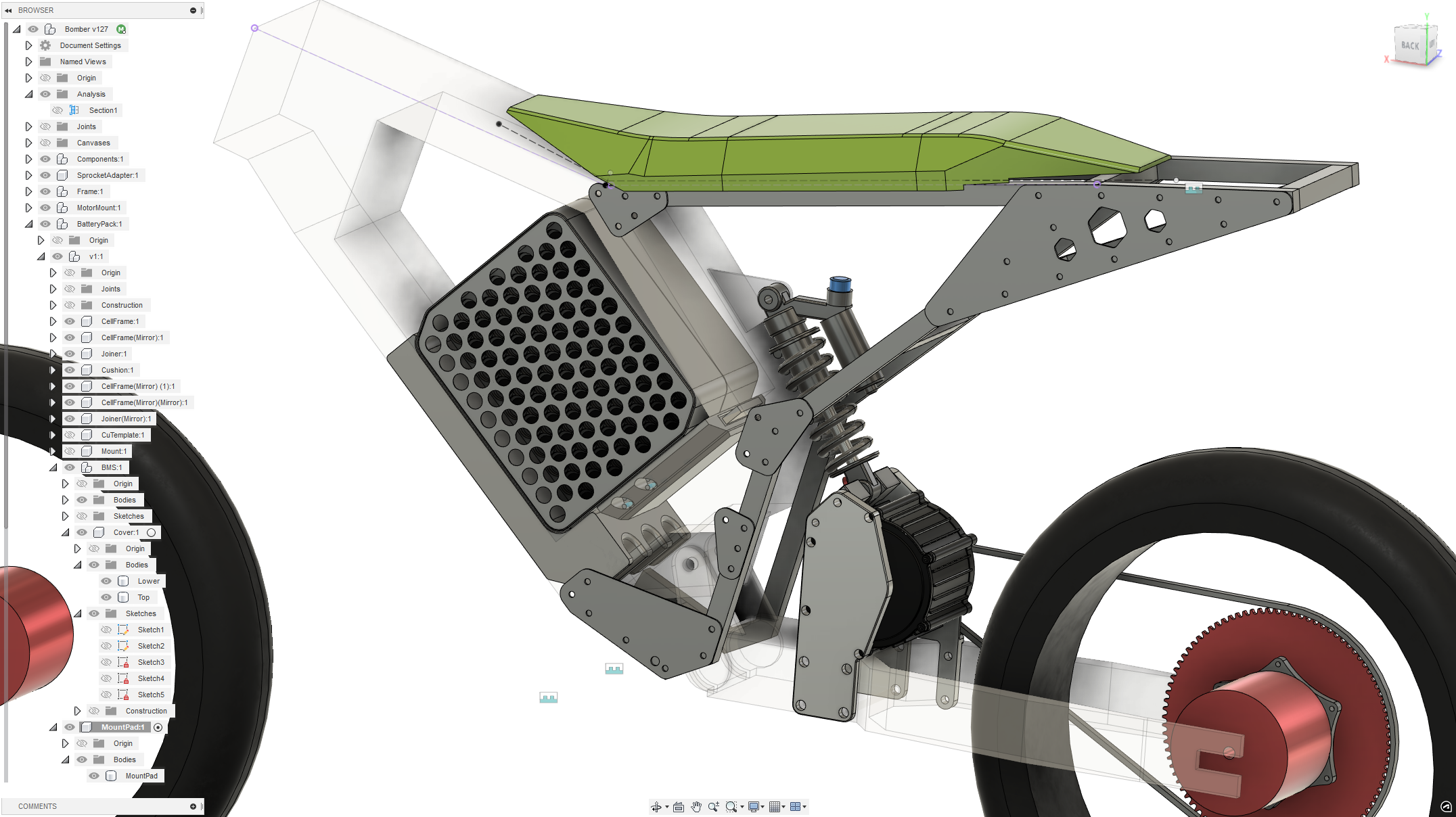
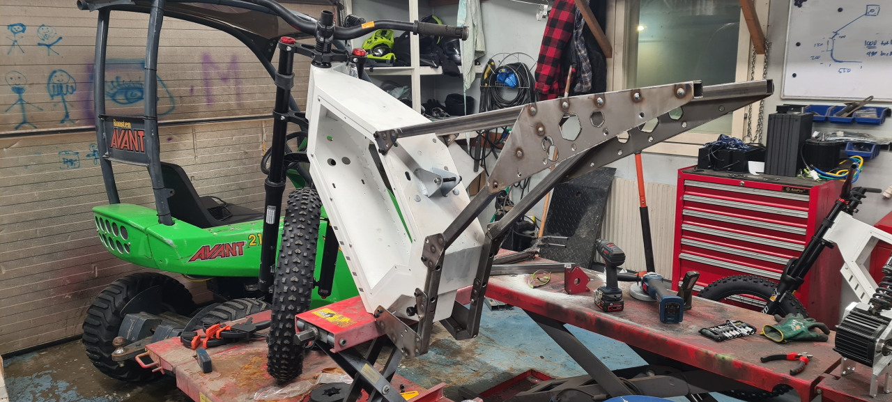
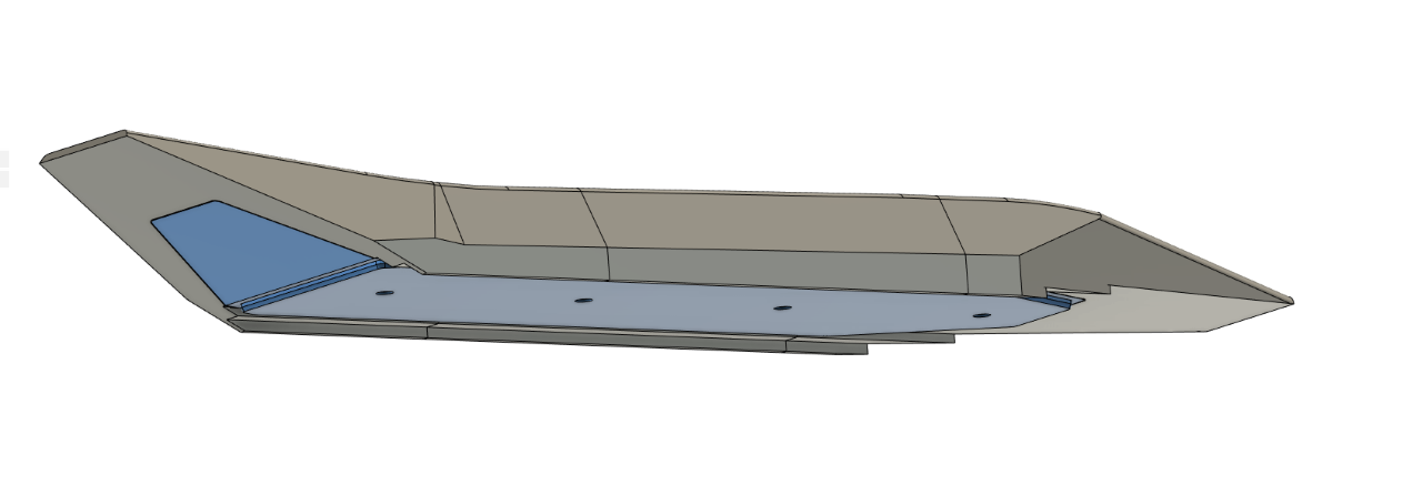
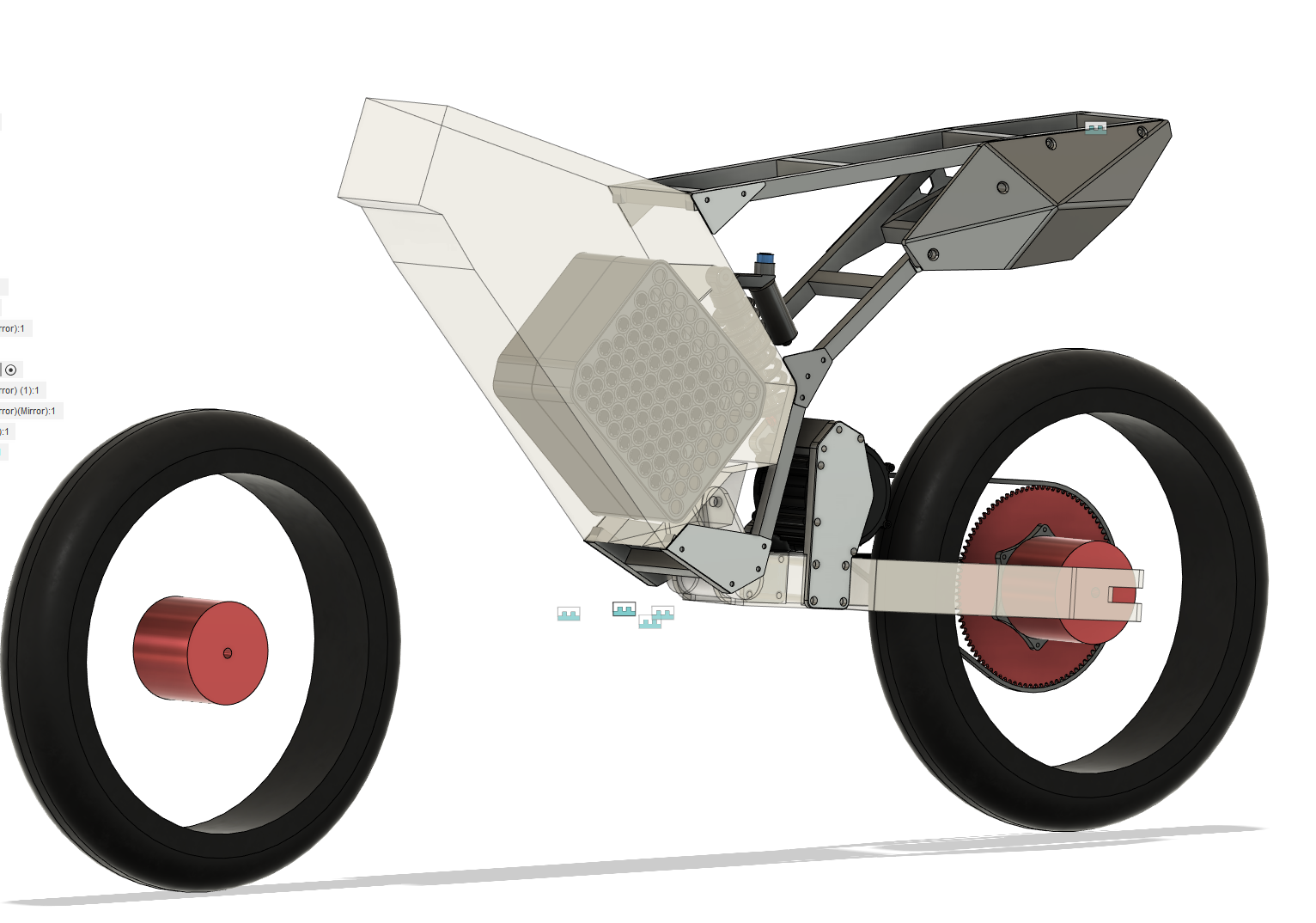
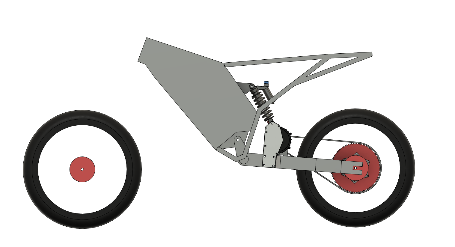
This is where the CAD is currently at. I’ve printed the first iteration of the back plate and am going to fit that on the bike today as I’m milling the adapters for the rear wheel.
I’m trying to make shorter and more frequent updates but as it is now the project stands still for huge amounts of time while I CAD and design and print stuff, and then I’m making progress that shows in a few days.. so I’m doing my best to keep everything updated.
Thanks for reading and if you’ve got questions or comments please post a comment on here or reach out on facebook, instagram or discord.
To be continued..