So, yes, this happened.. :/
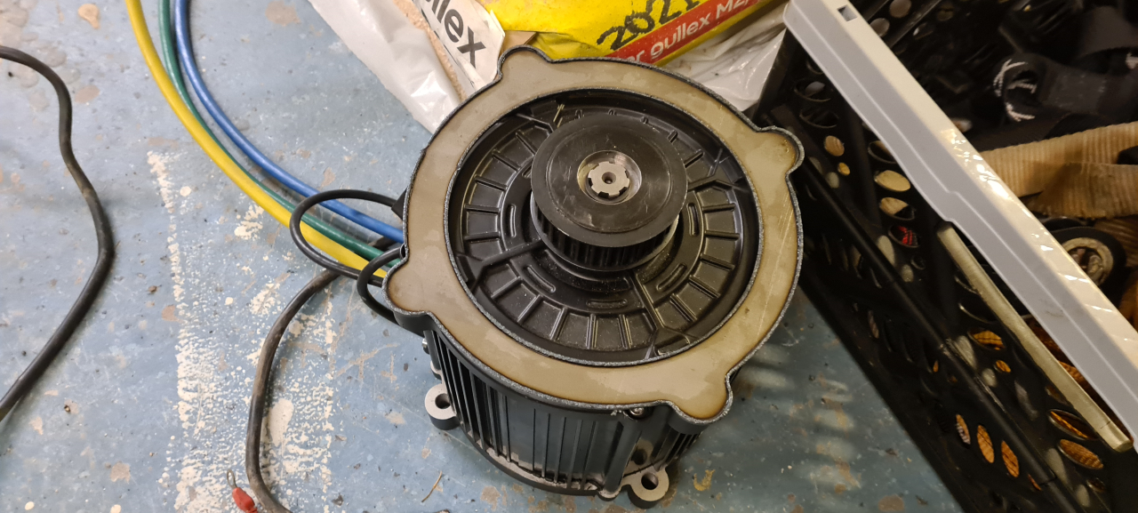
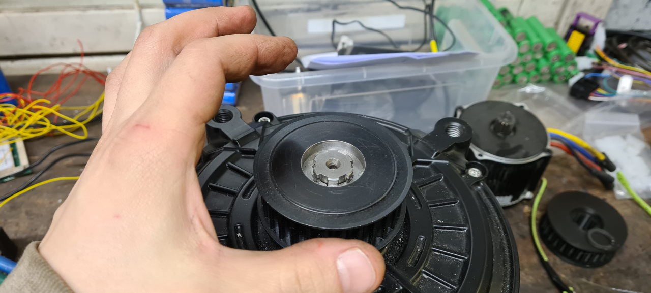
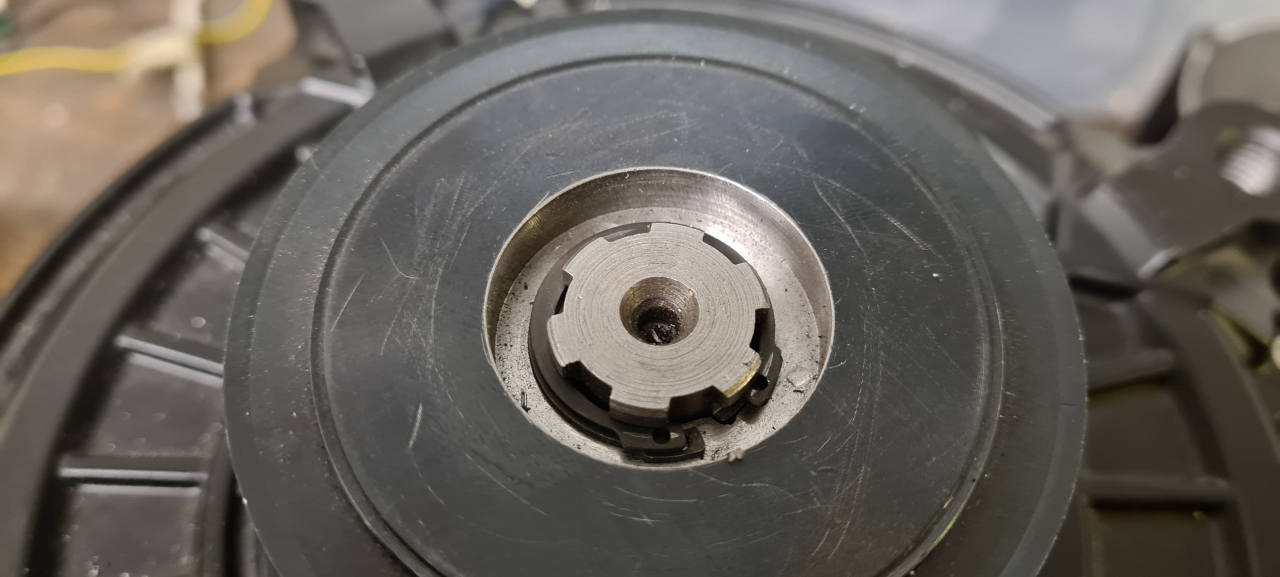
After running the evant for two charges the controller died. It starts, I can connect to it using the USB dongle but as soon as I give throttle input I get an overcurrent error.
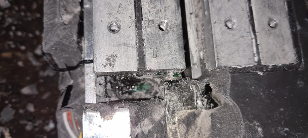
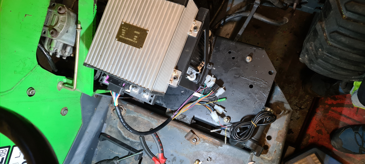
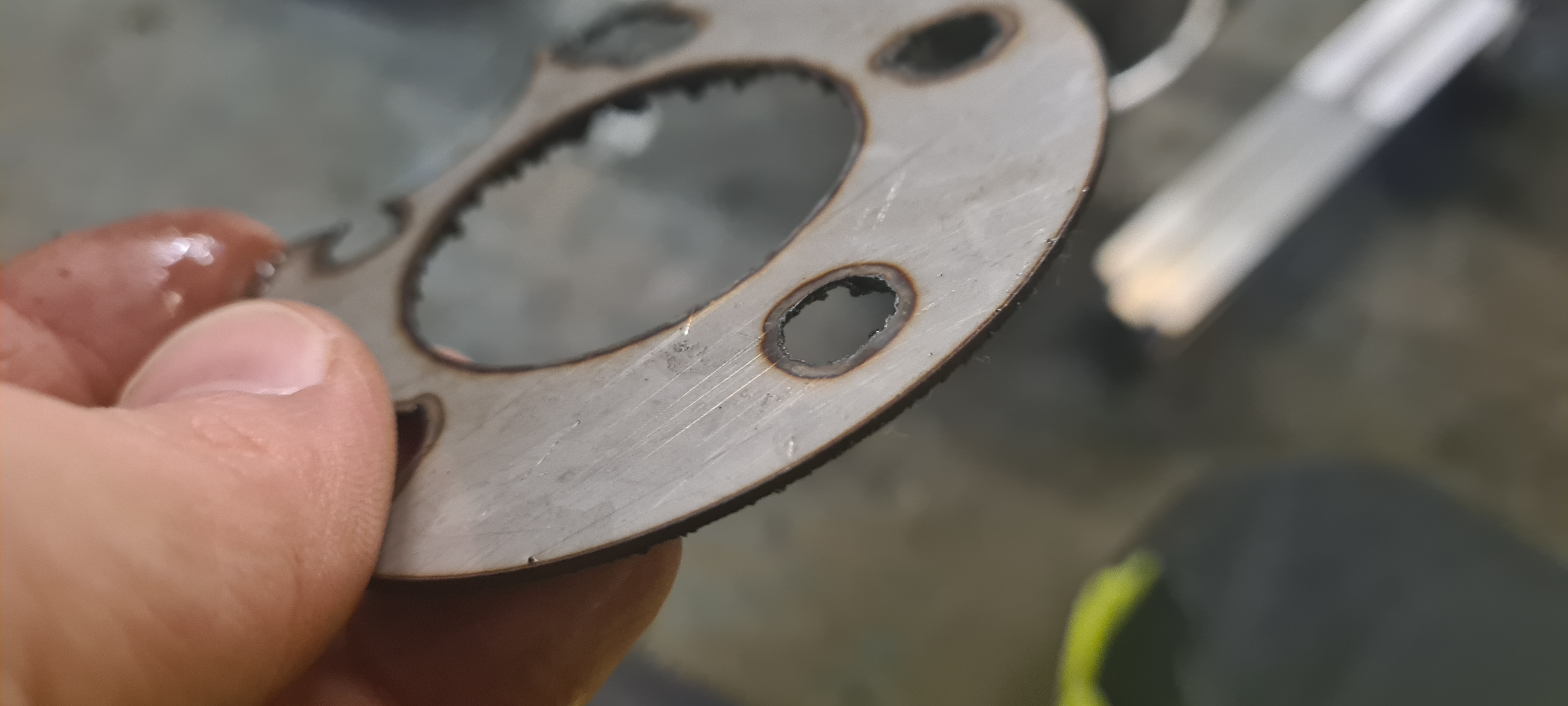
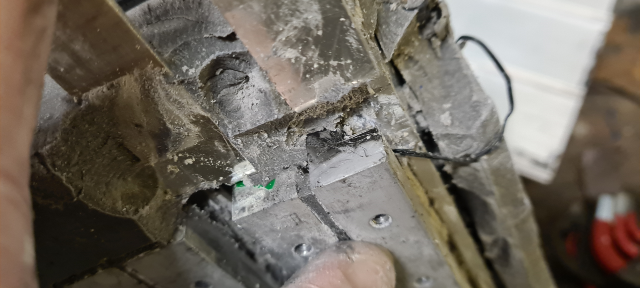
Measuring the phases it turns out that one phase is shorted to B-, typical mosfet failure. QSmotor, that I bought the motor and controller from, was reluctant to send me a new controller even though they state there’s a 1year and 3 month warranty period. Somehow they say I damaged the controller but it’s virtually impossible to damage the controller in this way except when assembling it. In the end they offered for me to send the controller back to be repaired, or pay half the price for a new controller.. I chose to send it back, which it turned out was not a viable option at all.. so..
The problem with buying a new controller at half price is that Shanghai is shut down due to Covid and the factory is closed.. so QS couldn’t really tell me when I could get a new controller, so the Evant project halted..
Until..
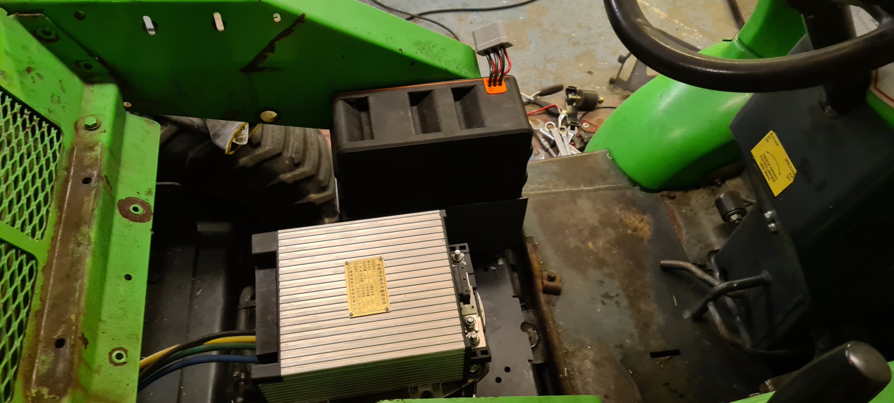
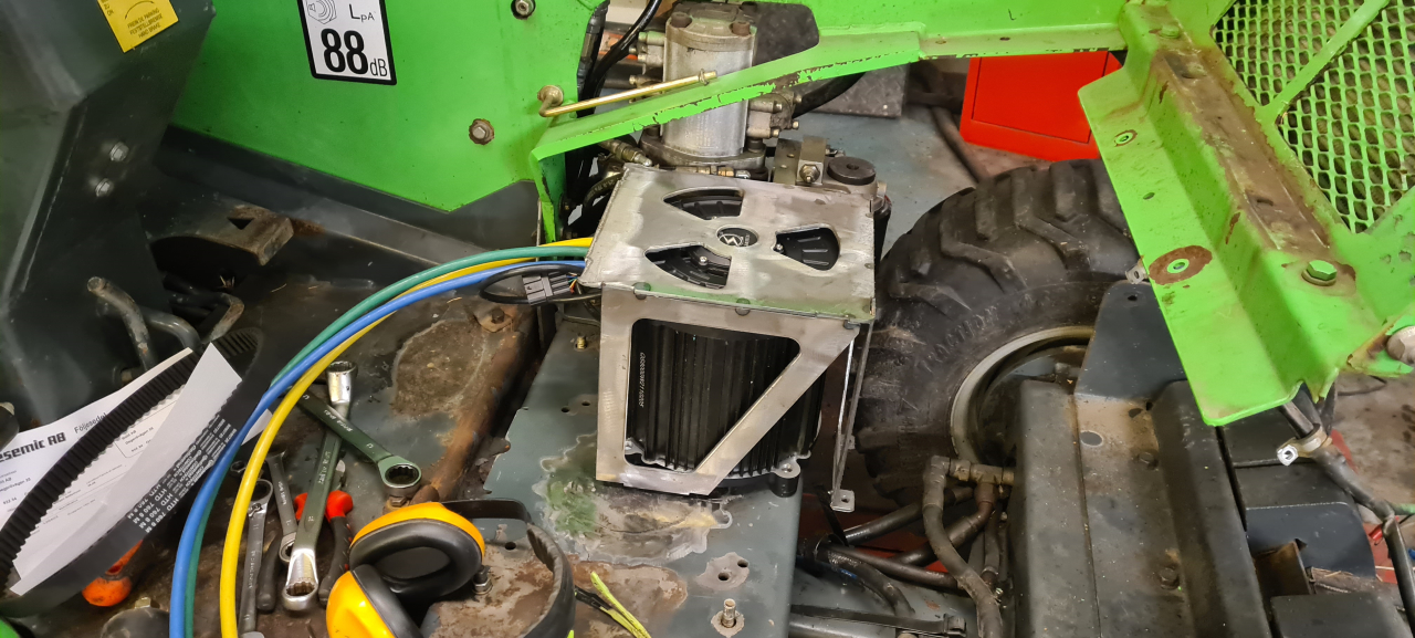
I’ve already started planning my next project. It’s going to be a couple of awesome dirtbike replacements.. powerful LightningRod bigblock motors and matching ASI BAC controllers. More on this later. The thing is, I’ve already bought and got the motors and controllers. So.. I started out connecting my 50A VESC to the QSmotor, just to try it out, and sure – it runs. Wierd that the 800A APT96800 controller got damaged from pushing the same amount of power that a 50A VESC can handle.. well well..
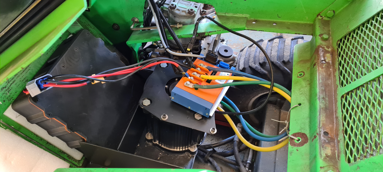
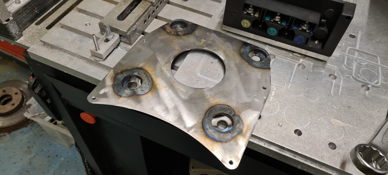
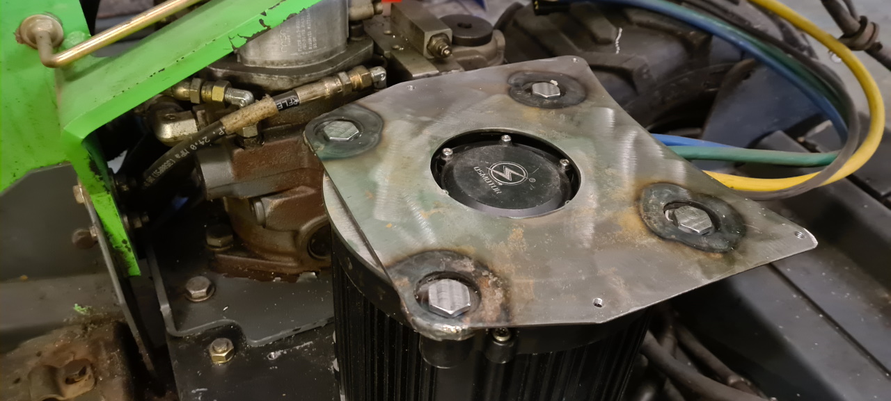
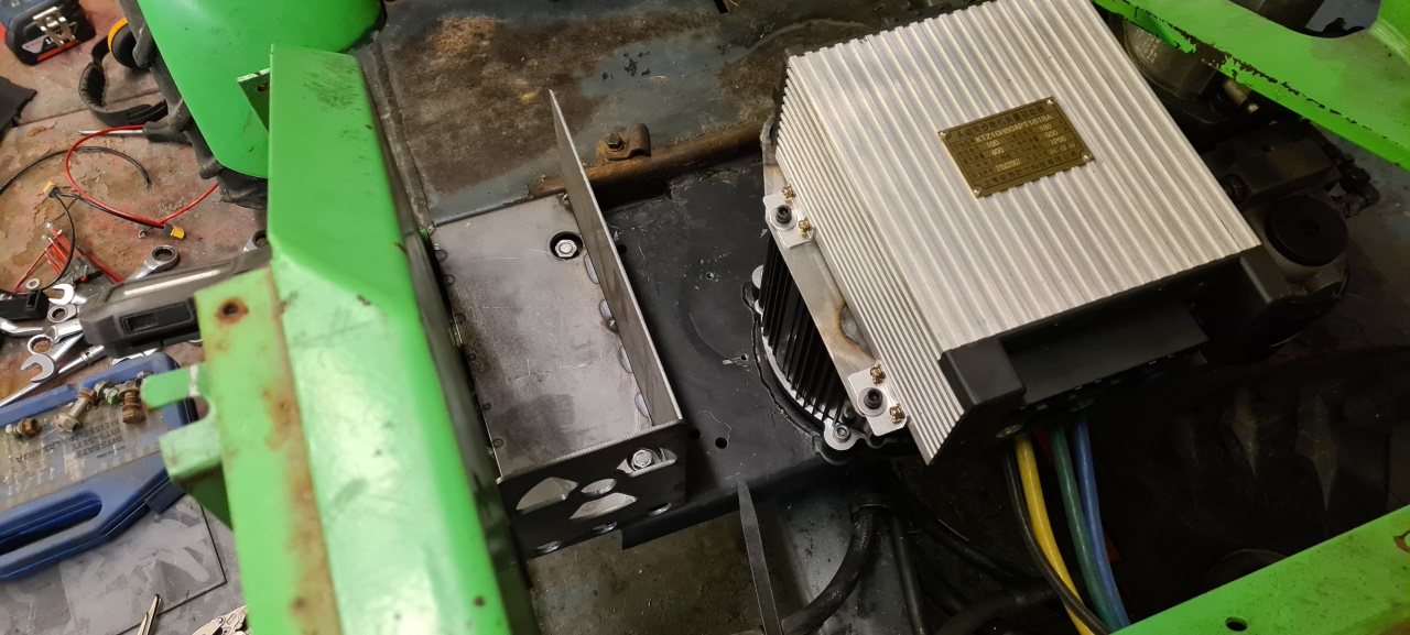
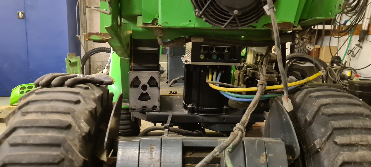
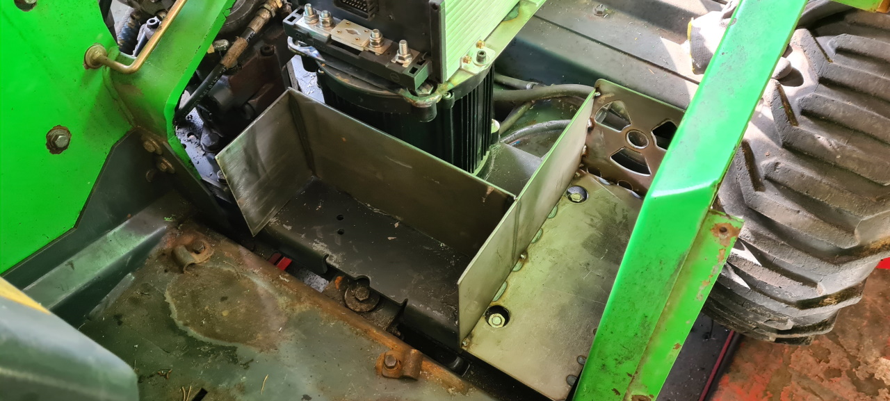
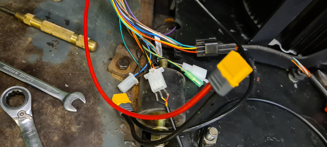
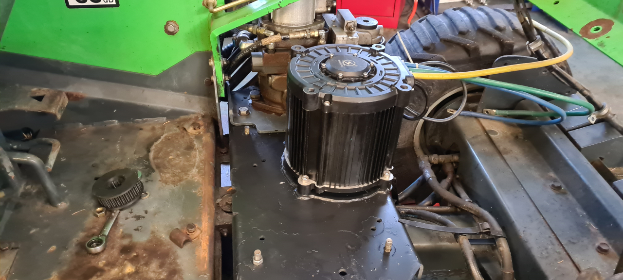
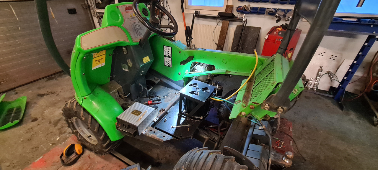
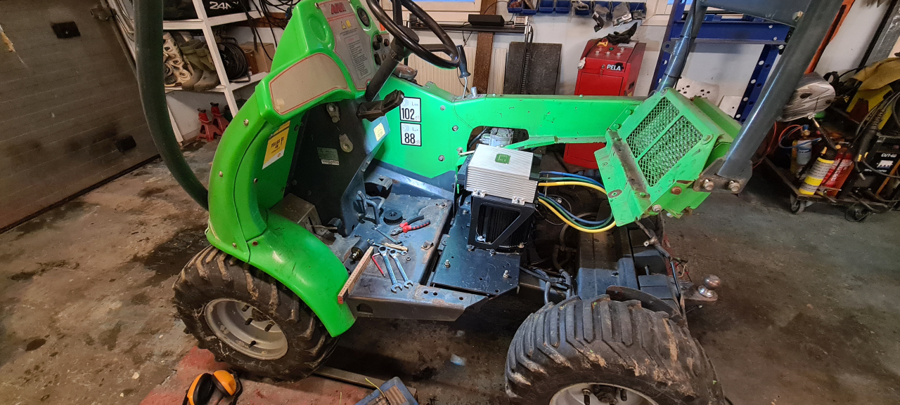
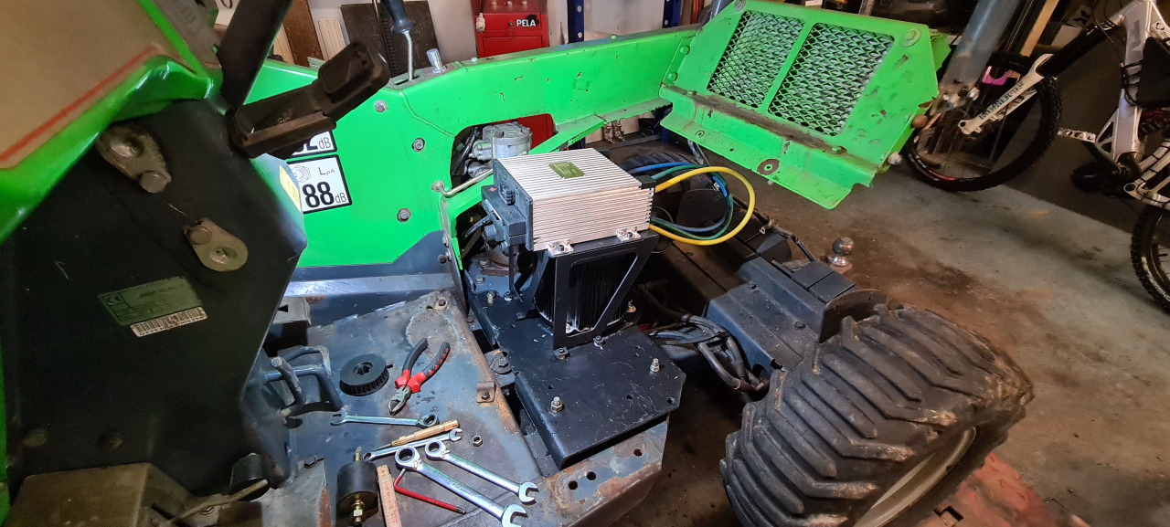
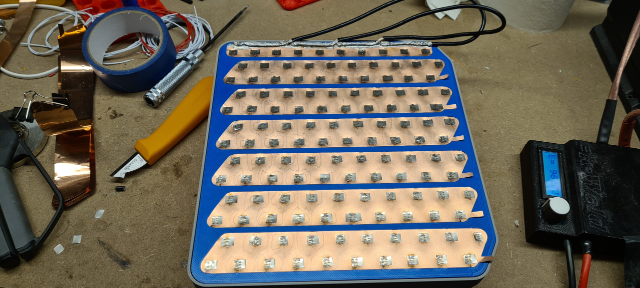
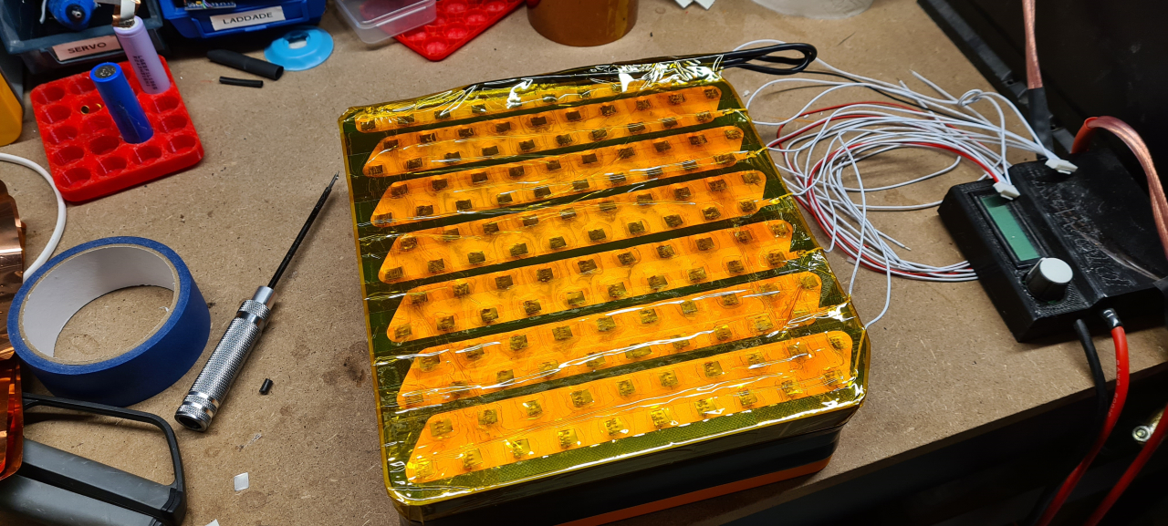
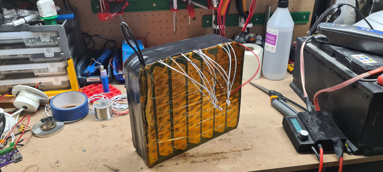
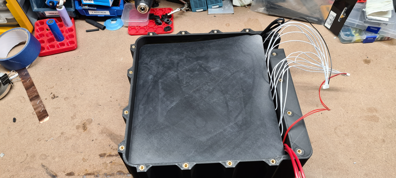
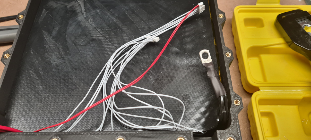
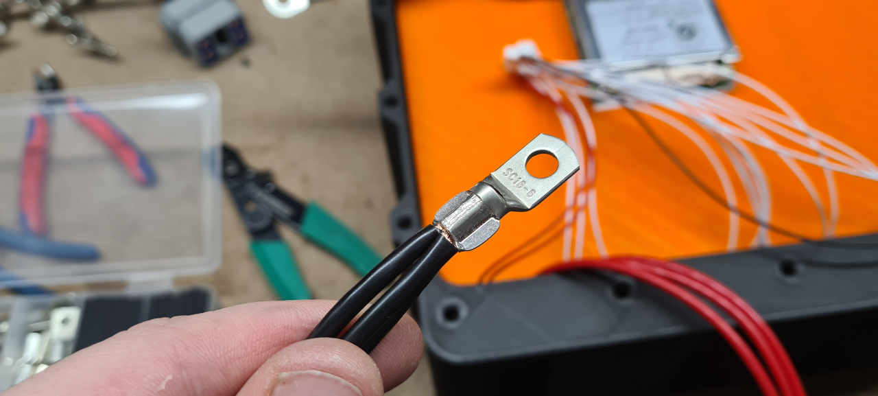
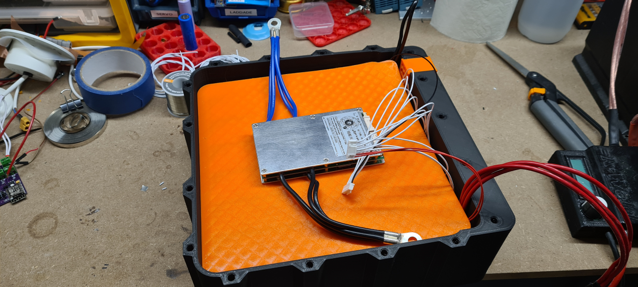
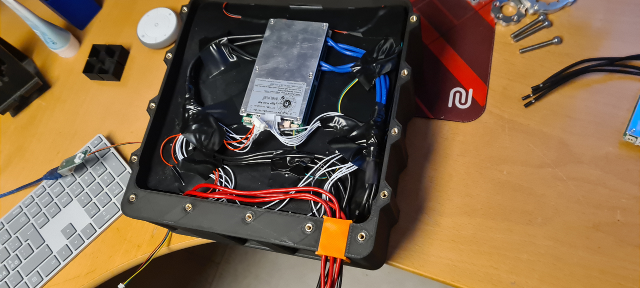
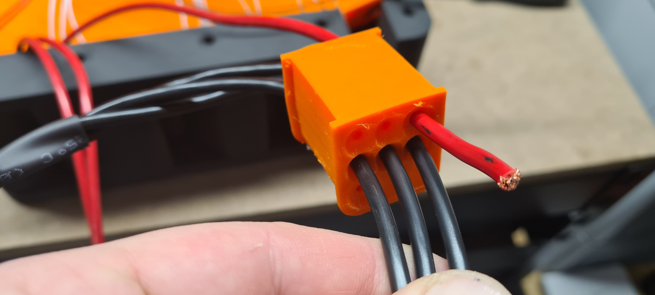
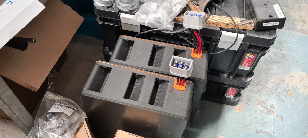
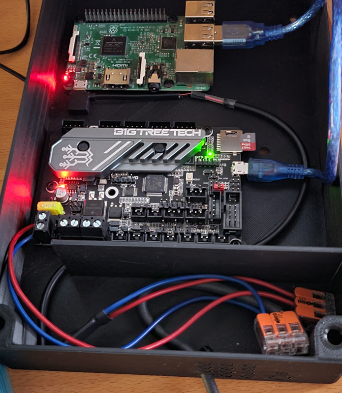
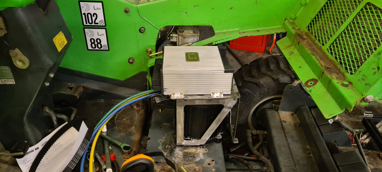
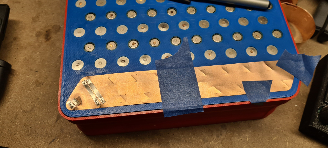
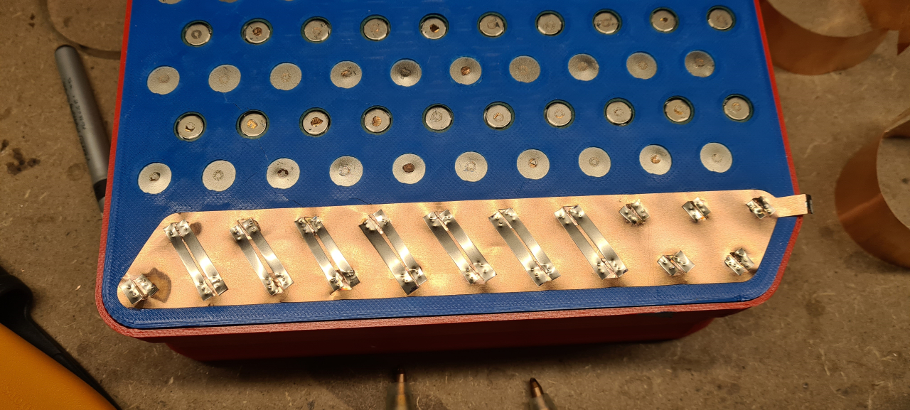
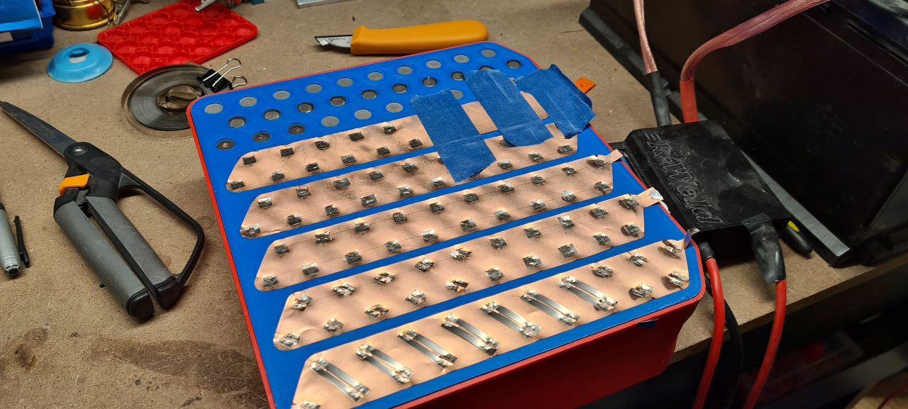
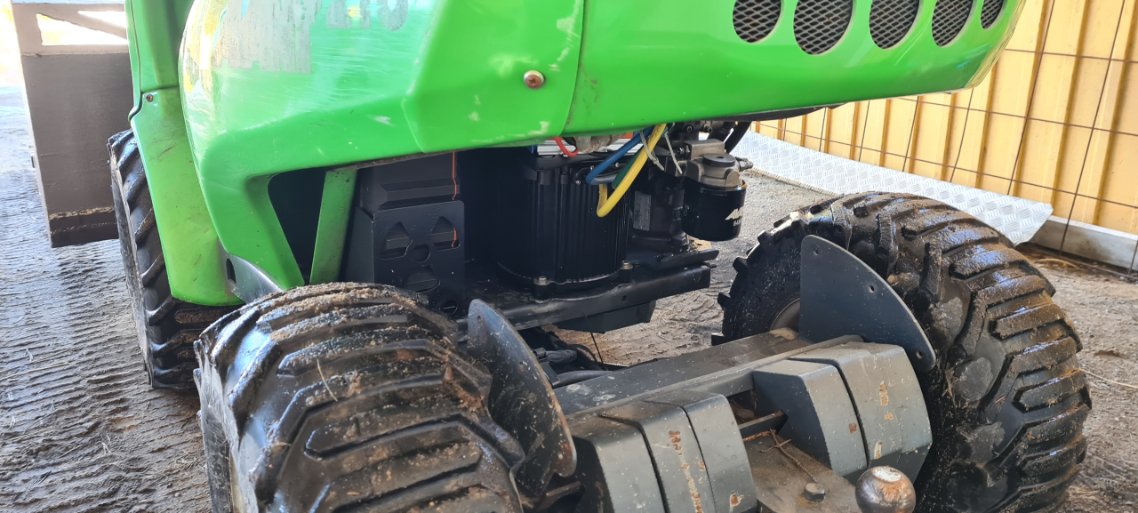
For my build I’m going to use the ASI BAC4000 controller. It can handle 400+ phase amps but is limited to 72V max nominal voltage on the batteries. Since I’ve already built the 48V packs that’s going to be utilized in future projects as well, I’m running the Evant on two 48V packs in parallell yielding 60Ah and 2,9kWh. After discussing the matter with mr HV on the HV discord I connected the BAC4000 to the QSmotor and made connectors to precharge and connect the two packs in parallell.
One problem with this setup is that the QS motor uses an encoder to keep track of the rotor position while the ASI BAC only supports hall sensors.
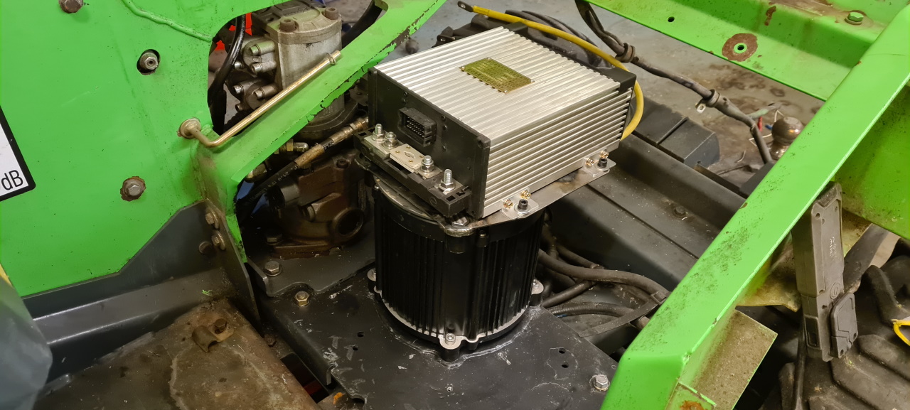
But it turns out the BAC4000 actually handles the motor better in sensorless mode than the APT96800 did using the encoder. 😀
With the APT the motor sometimes stalled, loosing sync, requiring me to turn the machine off and on again for it to regain sync. The BAC4000 hasn’t lost sync once during the hours of use I’ve put it through.
Well, now that the machine runs again it’s time to finish the project. Until now I’ve been driving the Evant with an android tablet in one hand keeping track of the battery status..
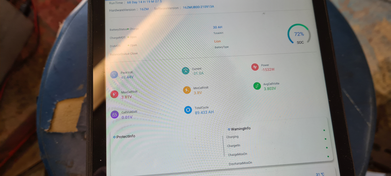
The ANT BMS is super with it’s bluetooth connection and app showing all the data you need, but it’s a bit cumbersome driving around holding a tablet all the time.
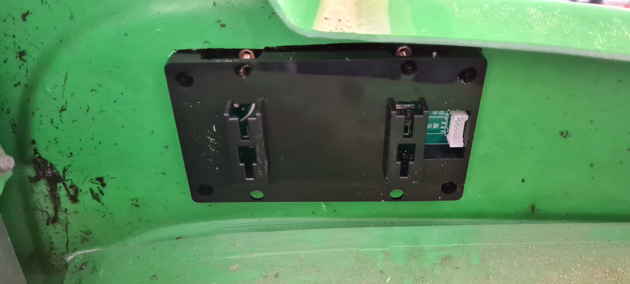
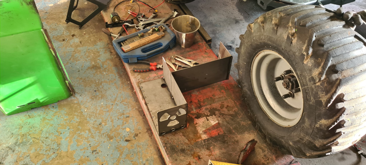
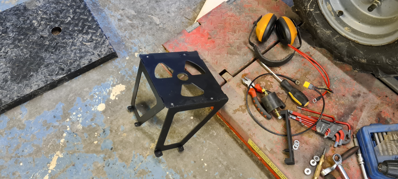
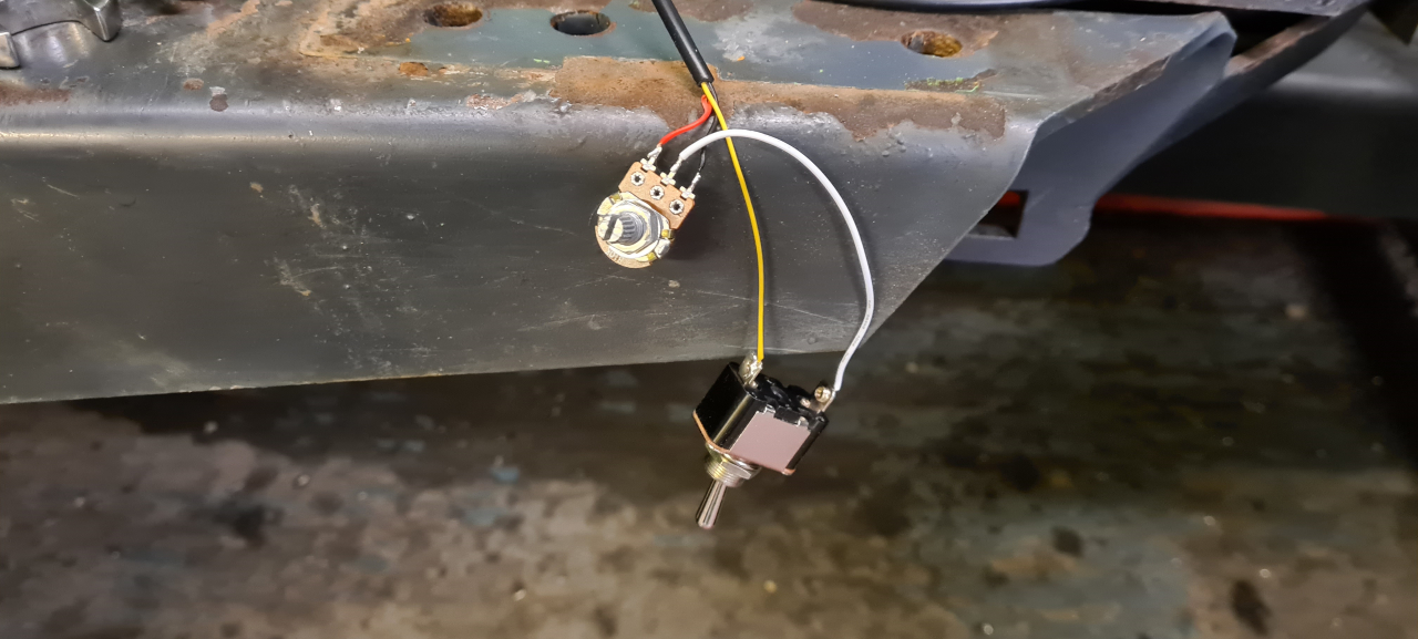
I got a display that connects to the BMS in the battery..
Printed a sealed backside and TPU gaskets for it..
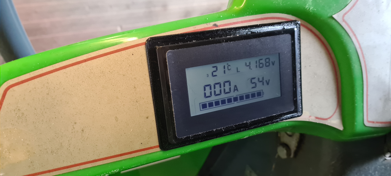
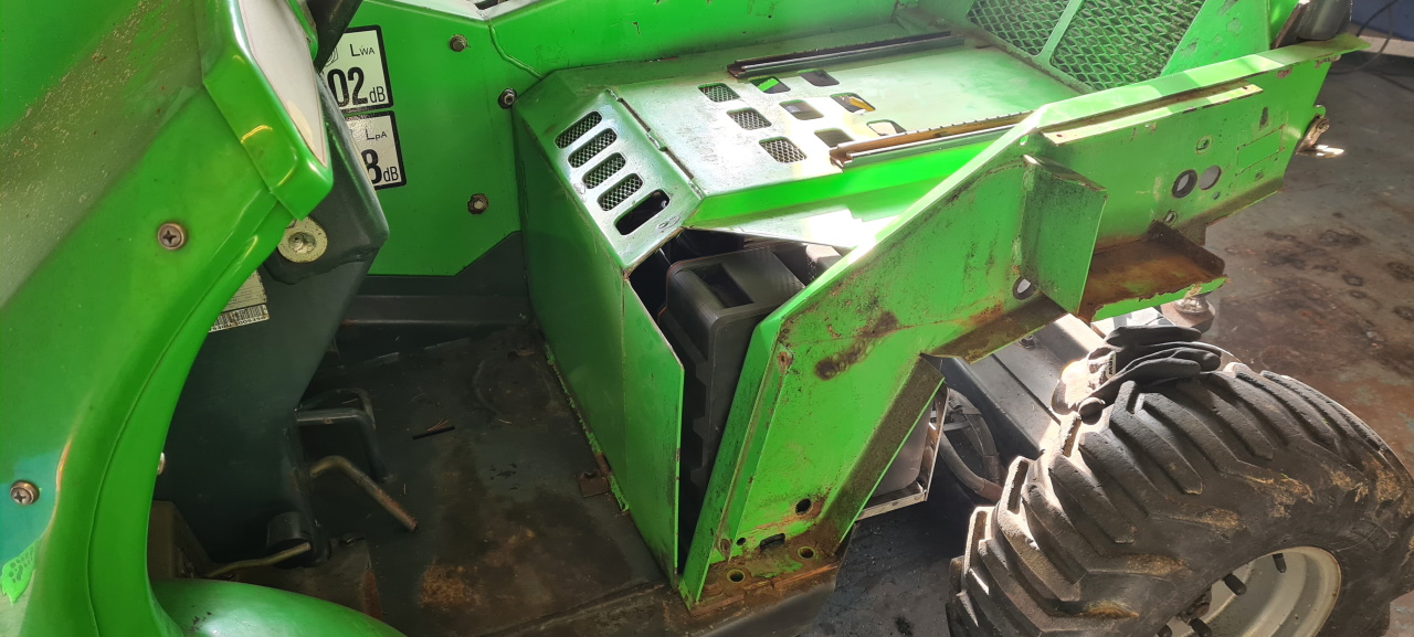
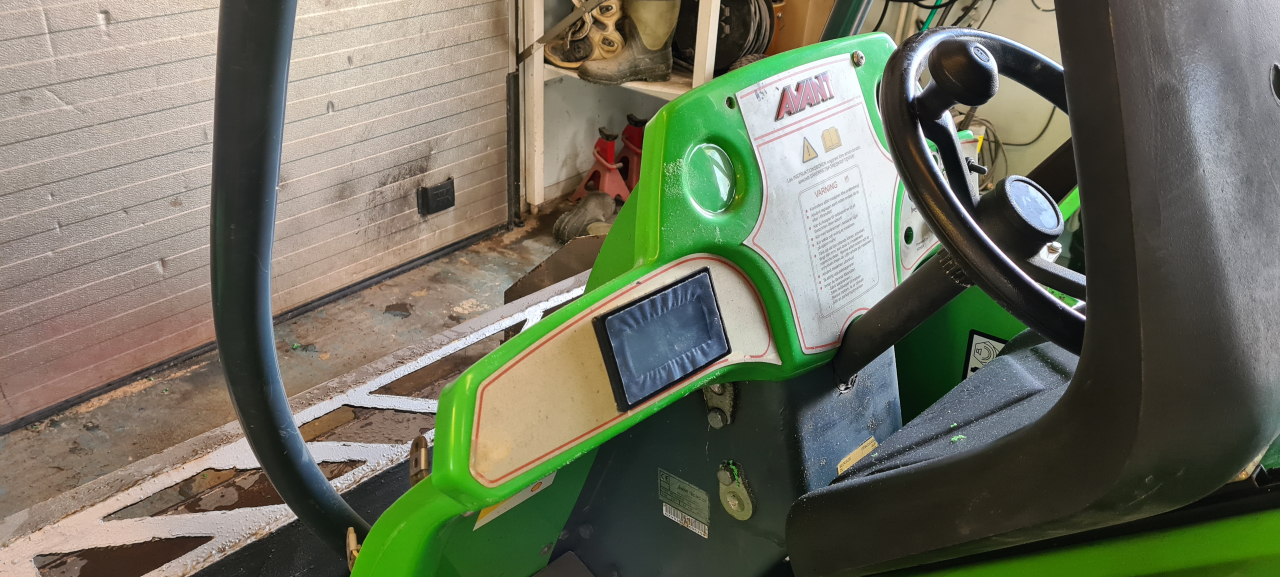
And viola, the last piece of the conversion is in place! The display shows the voltage of the battery, the temperature of all four temp sensors in the pack, the highest and lowest cell voltages and the current draw. Since the display connects to one BMS in one of the two batteries the actual current going to the controller is actually double what the display shows though. But now I can keep track of the battery status while driving the machine with two hands!
Today I’ve been moving heavy wet snow from our lawn just to test the Evant out. Turns out I can drive it for a little more than 50 minutes on a full charge..
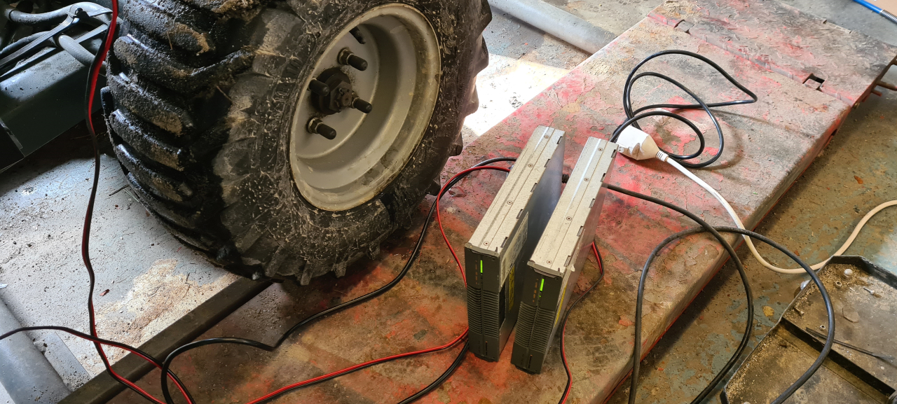
.. and then it’s time for charging. I got two of these Eltek Flatpack 1500 from a friend and they’re able to push a little more than 30A each into the packs.
Unfortunately one of them had a problem with the voltage regulation and died after charging one pack but with these chargers I can charge one set of batteries in approx 45 minutes. This means that with 2 sets of batteries I should be able to run the machine back to back assuming the motor or controller doesn’t overheat.
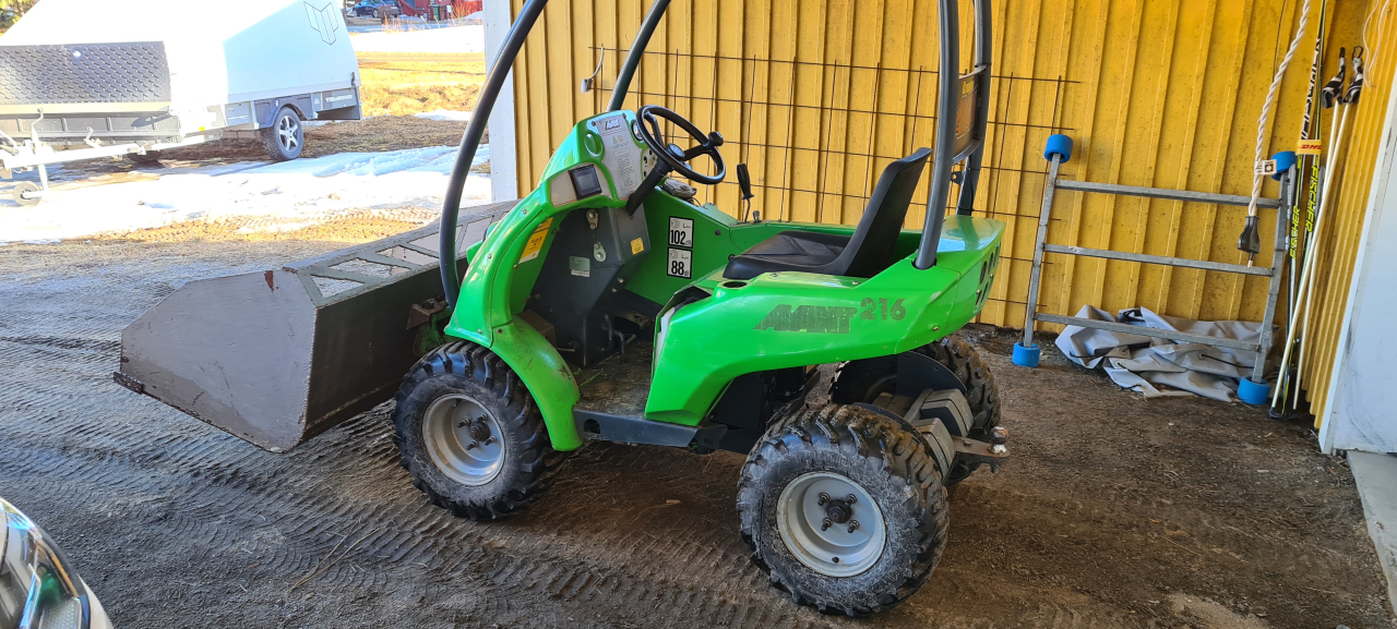
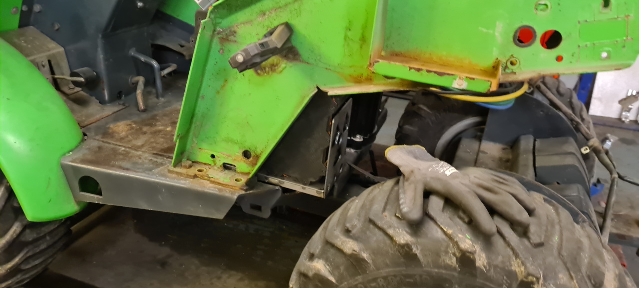
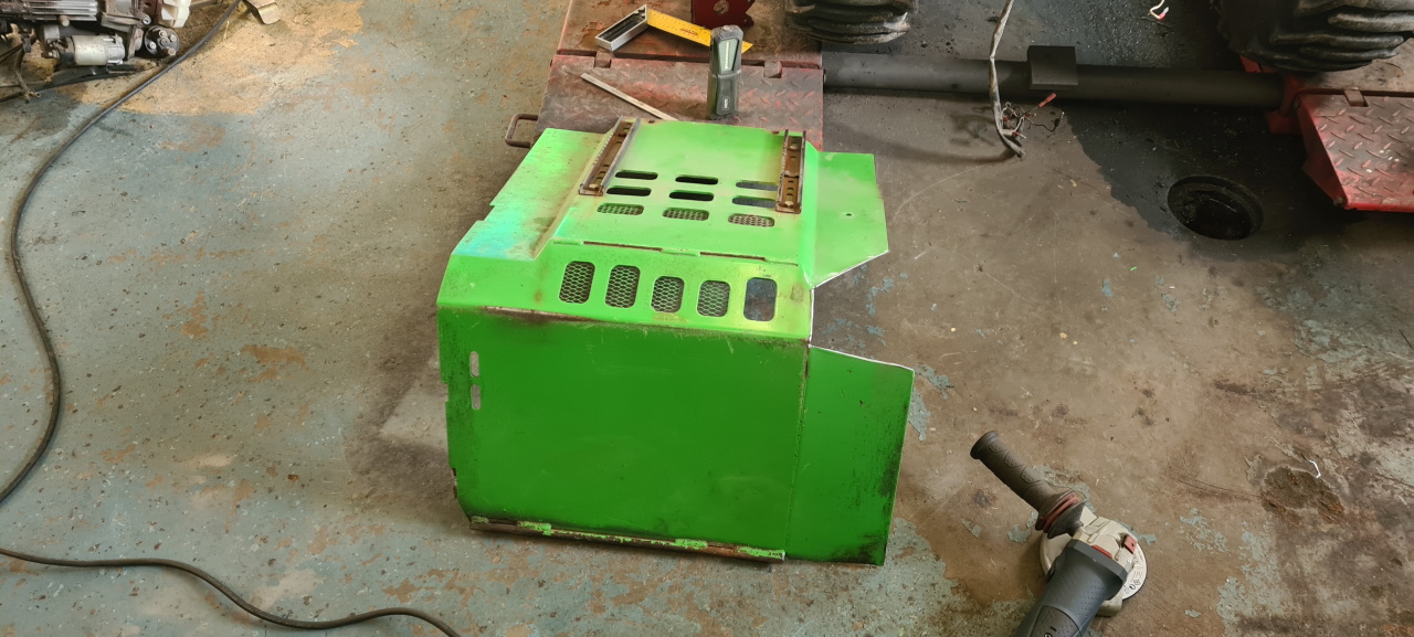
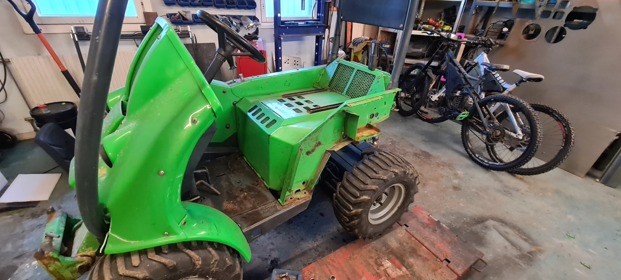
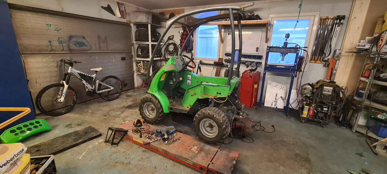
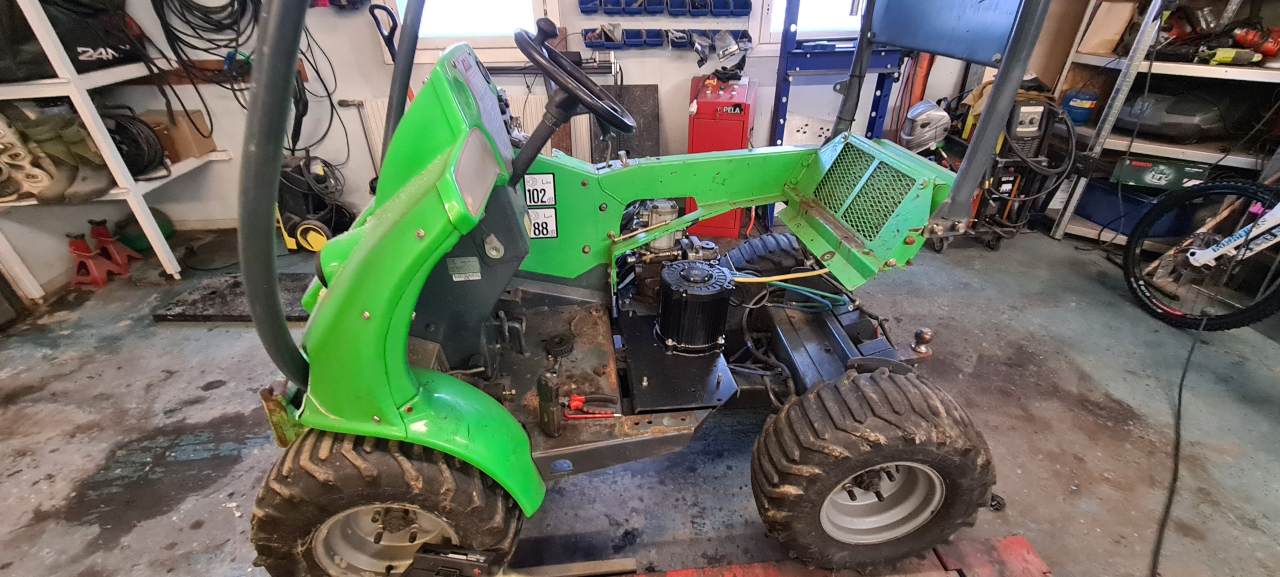
So now the build is more or less complete.
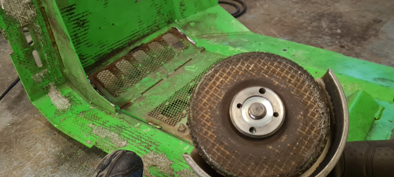
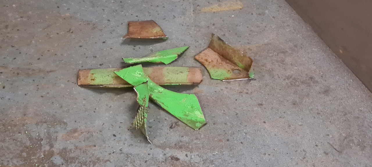
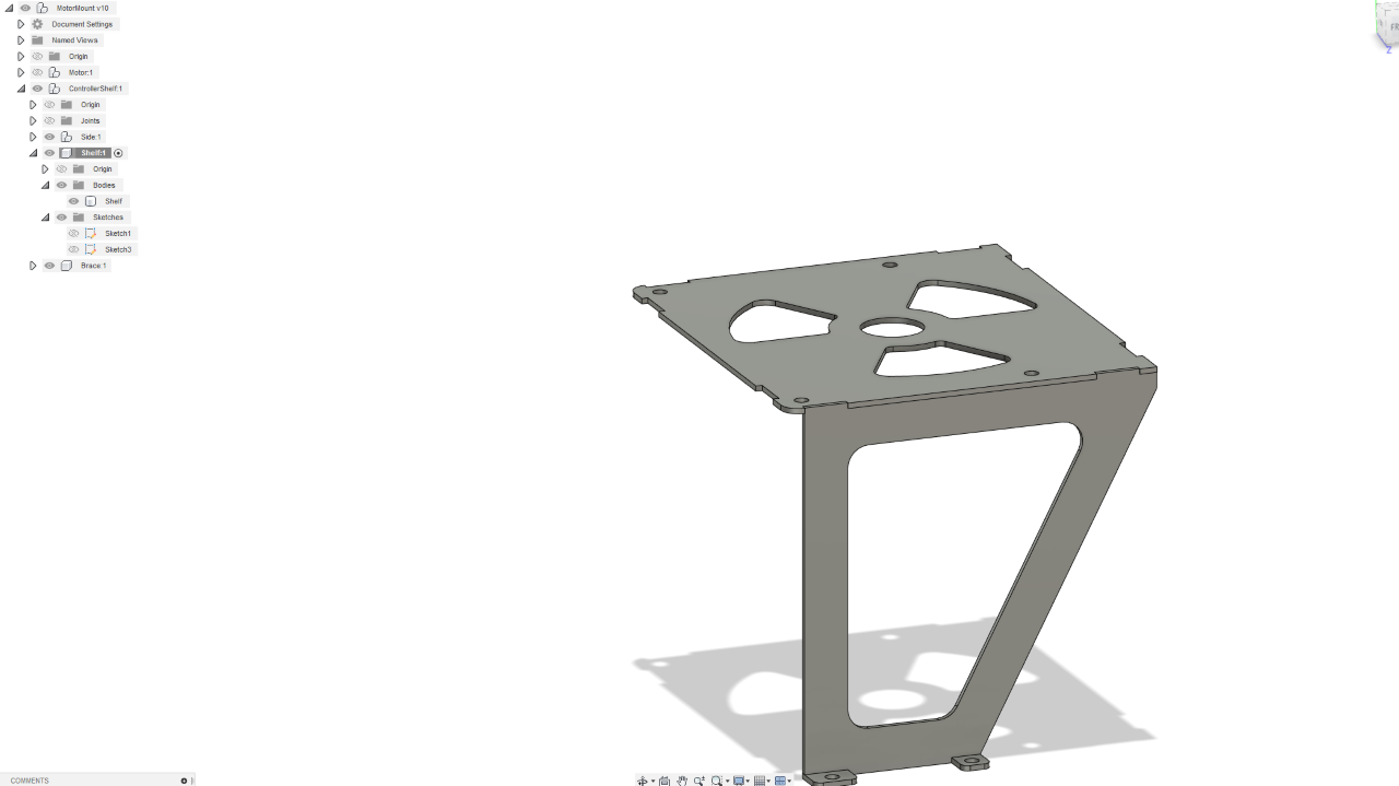
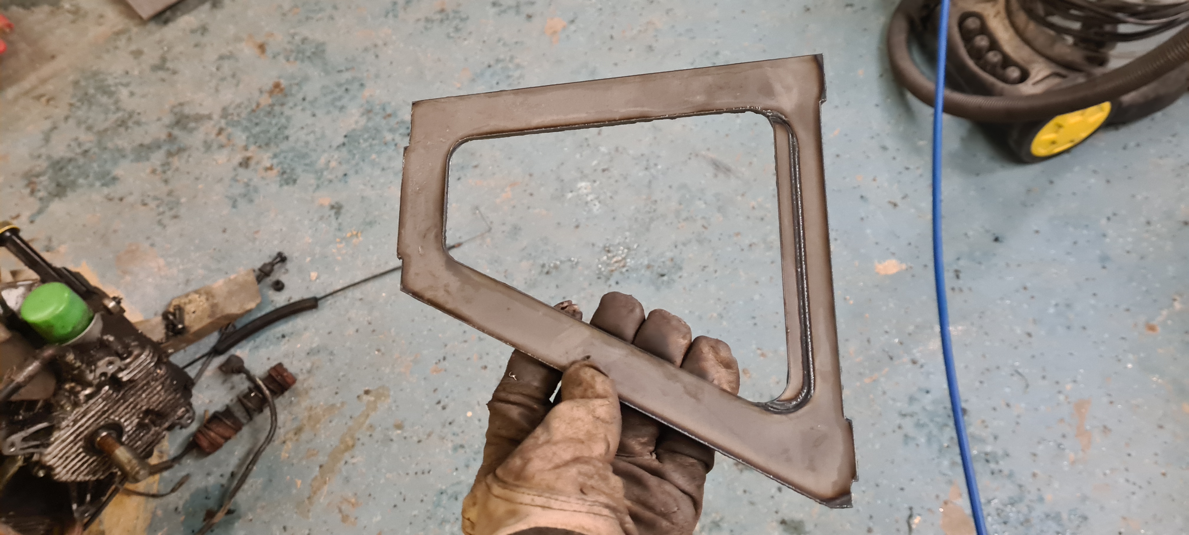
I’ve got a few panels to remount that I need to repair first but the machine is definitely ready for use again.
Testing the limits of the battery I ran out of juice in the middle of the driveway..

So I had to get the charger and charge it for 10 minutes to be able to drive it back into the garage. =)

When stuff goes sideways like this it truly helps having good people to turn to. The Evant is running again thanks to the awesome help from Captain Codswallop and mr HV on the HV discord. They helped me tune the BAC4000 for my setup and have been super helpful in making the right decisions and making a wireloom that fits my needs. If you want to build a high power ebike or just make any kind of electric conversion I really recommend joining the High Voltage Light Electric Vehicles discord server.
Also, check out the HV channel on youtube:
https://www.youtube.com/c/HighVoltageKits
Well, that’s that. I’ll post further updates if the controller or motor fails, but for now this project is more or less finished! Hope you’ve found it interesting!