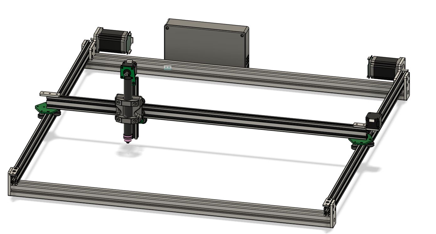
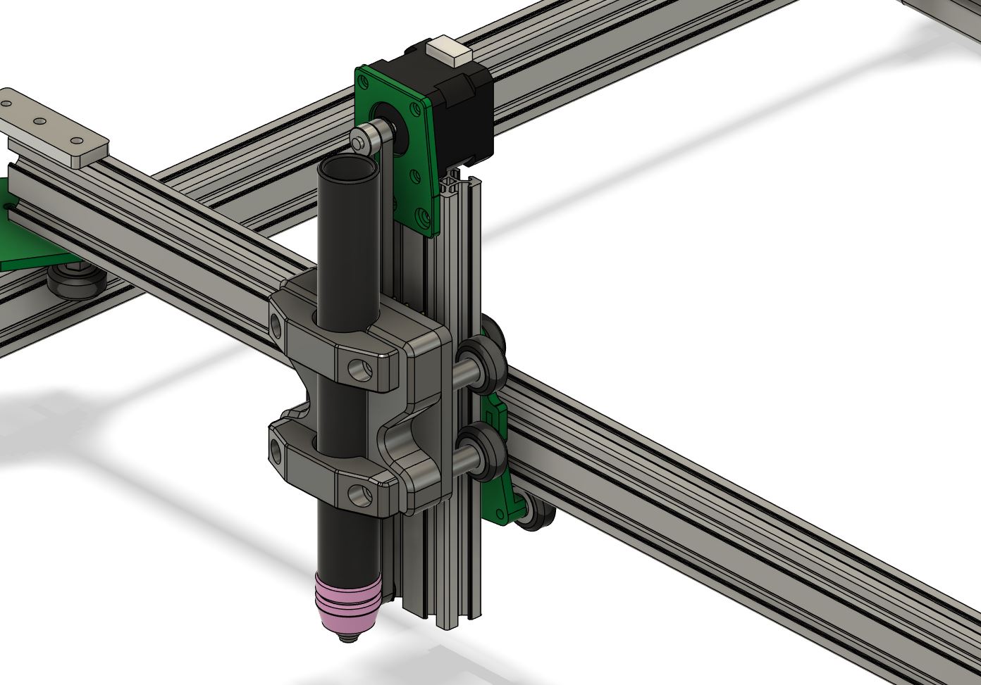
On popular request I’ve exported the CAD to STEP format for sharing. I’ve done a quick cleanup of the file and all parts named _NOTUSE are not to be used. Most of the custom parts I’ve milled from aluminium but a good 3D print should work just as fine.
If you download and use the file please look at it as a template and feel free to improve wherever it needs improving. My plasma is running with a CUT60 chinese plasma cutter and working fine.
Also, if you build the thing I’d be happy to hear back from you. Please post a comment here or on my youtube channel, https://www.youtube.com/@marcusrunsten and post a link to your build.
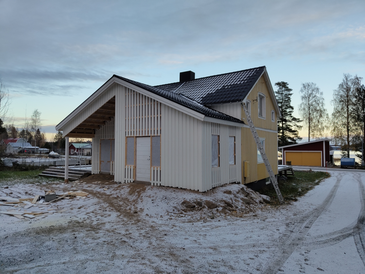
So, I’ve recently gotten questions about the lack of updates on here. The reason is this – we’re in the middle of building an extension on our house and that takes pretty much all of the free time I have at the moment.
Snow is starting to fall though, and ice is setting on the water. I’ve gotten studs for the fat-wheels and soon we’ll hopefully be riding again.
Currently editing the video of the second bike build too, but that takes A LOT of time.. we’ll see when that’s done.
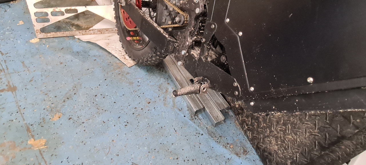
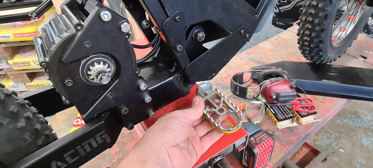
So, the footpegs I put on the bike were cheap, but not awesome..
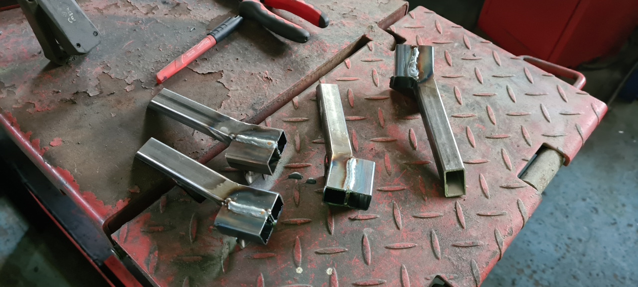
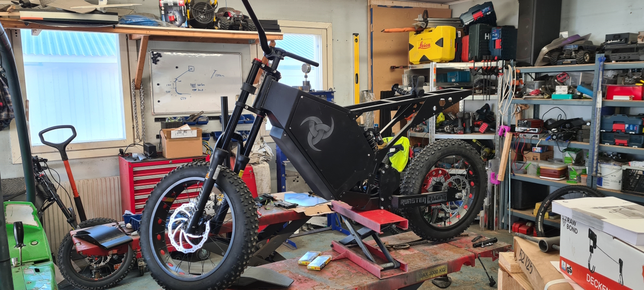
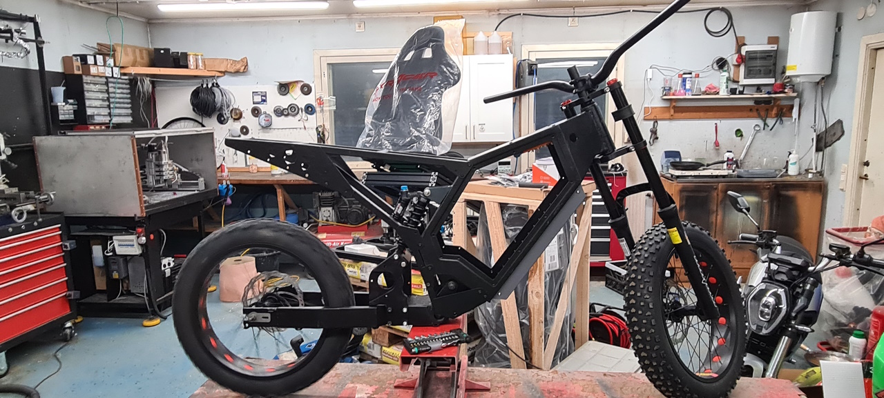
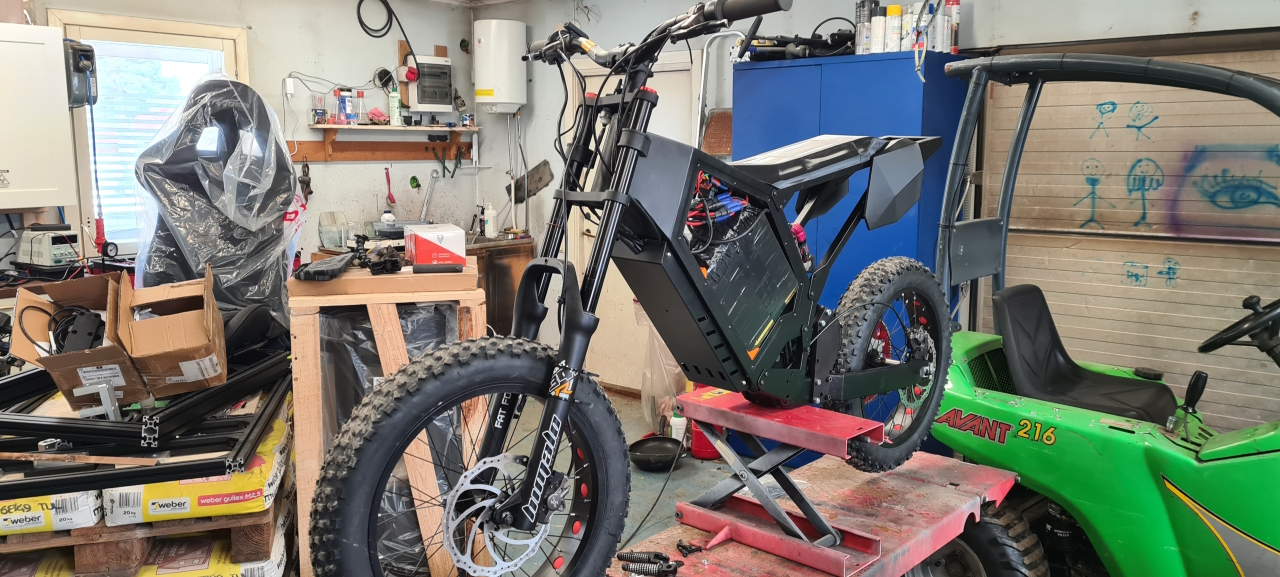
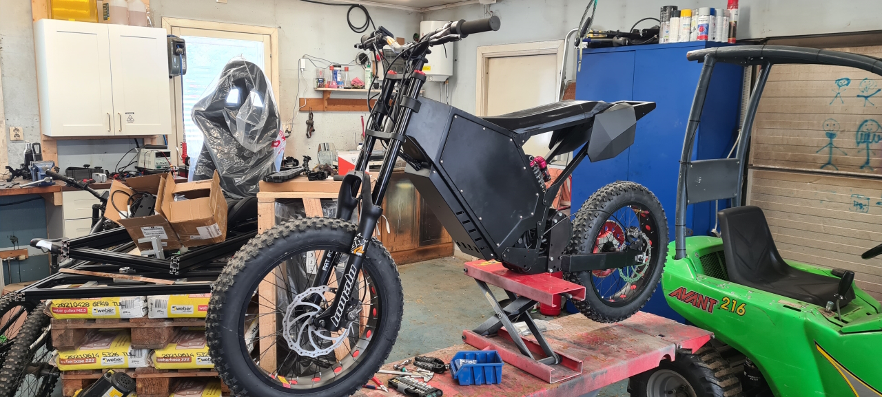
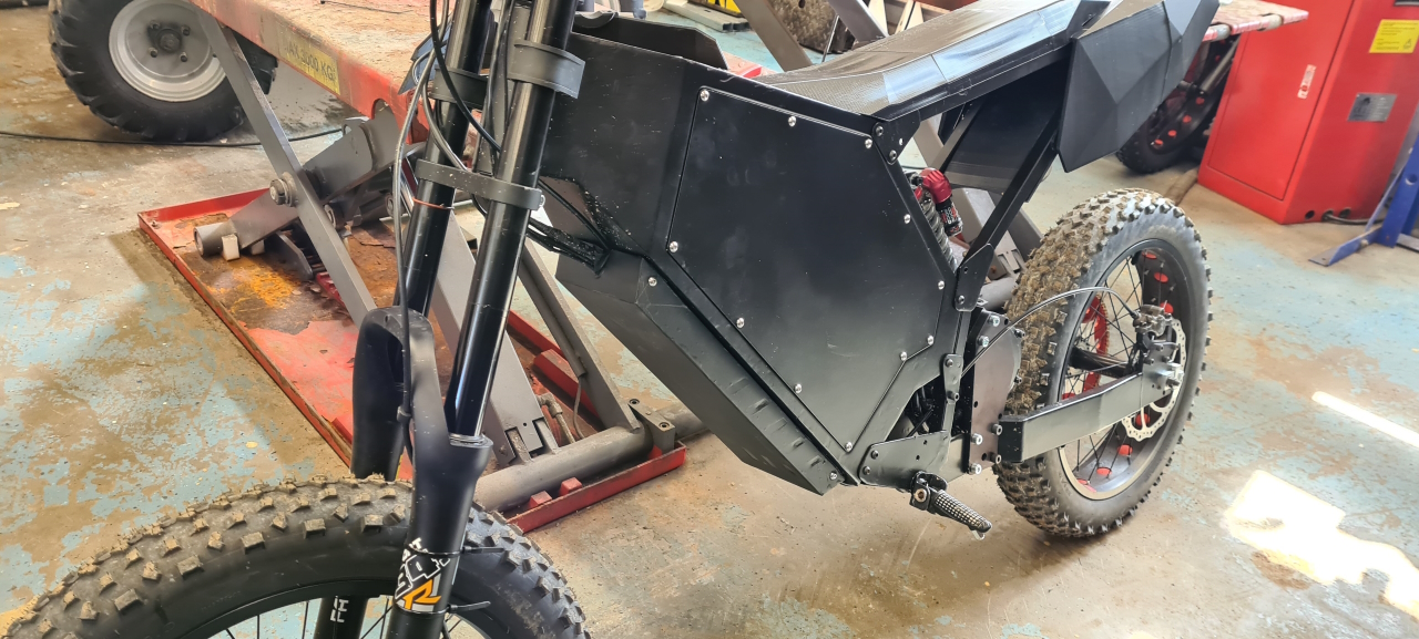
They were flimsy and didn’t give any confidence at all. They were also too close to the frame, and too far forward.. So, new solution:I got some proper footpegs at a great price, so I bought two pairs. These are a lot sturdier and more like the ones I had on my rally bikes. I’ll be mounting them about at the same position as where the BB would sit if I hadn’t put a custom subframe and footpegs on the bike. Feels a lot better when trying them out at that position.Today I welded some mounts for the new footpegs. Hopefully I’ll get time to finish them tomorrow so that we can try them out. Since the frame is all powder coated and nice these will be bolt on, after finishing, sanding and paint of course. So, this is about how it sits at the moment. Not too much left to do. I’ll have to wait for the new 99T rear sprocket and will try out a custom milled 11T front sprocket. It’s milled from aluminium at the moment which probably won’t last. When it fails I’ll either put an 12T I bought on ebay on there or I’ll mill the 11T from steel. I tried to make an 10T but the 12mm shaft is just too big, there’s no material left around it with a 10T sprocket.
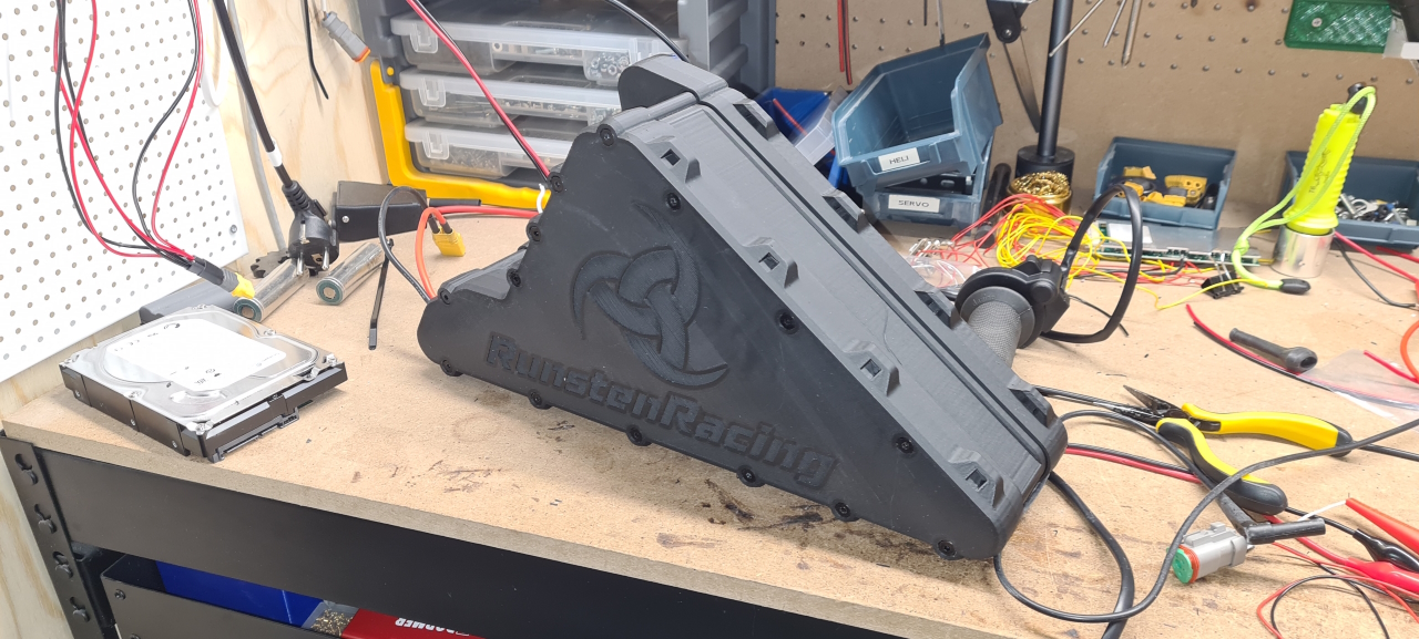
Also, I made stickers since I kind of like the black/grey color scheme.. What do you think?
When the bike is finished I’ll post a youtube video of the entire build. I’ve also got a lot of questions about what components I’m using and the total cost for the build. I guess I’ll put a BOM together and take on the dreaded task of figuring out how much $$$ these two bikes have cost me.. :/
As the bike I built for the kid was such a fun ride I expedited the build of the second one – for me. =)
Since I’ve documented the previous build here I’ll make a proper youtube video covering the build of this next one. It will have all the same components except for the controller which will be a BAC4000 where the last bike had a BAC2000. The reason for this is that I’m double the weight of the kid and I need more power to keep up. 😀
So, after finishing the sand blasting of the frames we took a break and celebrated easter in the cabin with some nice snowmobiling and relaxing.
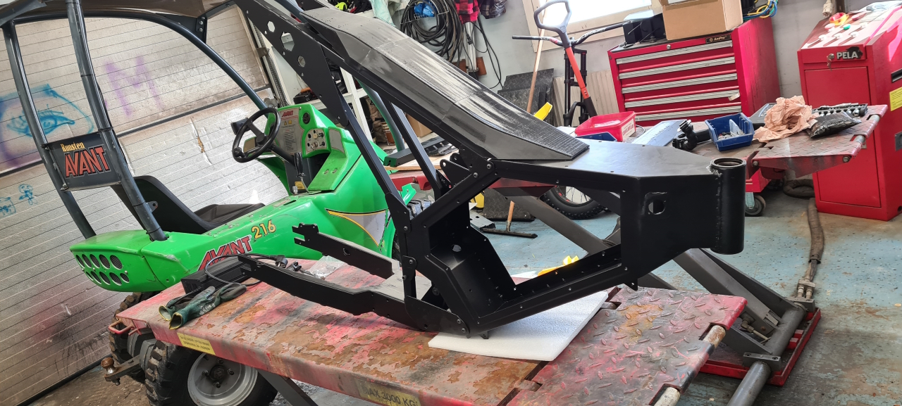
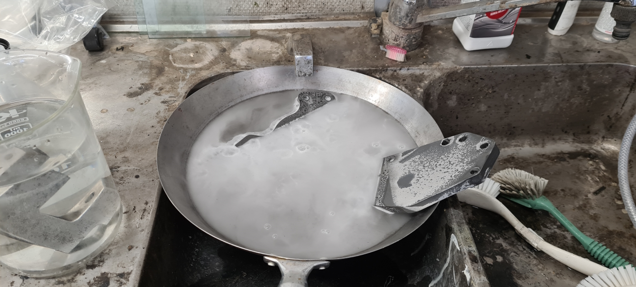
I spent more or less every night in a full week trying to get the paint off the frame. Considering the poor quality of the original paint it was surprisingly hard to remove.When we got back from the cabin my dear friend Nils had put new powder coating on all the parts with a stunning result!I must say I agree with my son, this frame looks much better in black! However having the nice looking frame I couldn’t mount the raw aluminium parts so I had to do something about that.After properly degreasing and cleaning the parts I let them soak in lye for half an hour or so. After the lye bath, inhaling loads of healthy hydrogen atoms in the process, the parts were properly rinsed and then the anodization process began. This is simply a bath of sulfuric acid and an adjustable power supply. The parts are submerged in the acid, the negative lead is connected to an aluminium sheet with a surface area equal to or larger than the part, and the positive lead is connected to the part to be anodized. This makes an oxide layer on the part that is a bit porous. The porosity and thickness of the oxide layer depends on the current flowing through the part and the time it’s left bubbling in the acid bath.
Since I wanted a thick uniform layer of color I let the parts anodize for about an hour at quite low amperage. The required current depends on the surface area of the part to be anodized but I usually kind of just guess and mostly it turns out OK. If not I’ll just redo the process from the lye bath and try again with different settings. =)
When the anodization is done I’ll just put the parts in a vat where I’ve mixed water and textile color, in this case black. The thickness and porosity of the part, the properties of the dye and how much color you want the part to get decides the temperature of the dye and the time it’s left soaking. Since I don’t know the properties of the dye and want the parts to be fully colored black I left the parts in the dye for as long as it took to clean and anodize the next part. This again -usually- turns out OK, but sometimes it doesn’t and then it’s back to the lye again..
To seal the porous oxide layer the parts are boiled for about 15 minutes – again depending on the properties of the oxide layer and so on. I’ve precviously had the water wash some of the dye out of the part so now I boil the parts while still in the dye bath.
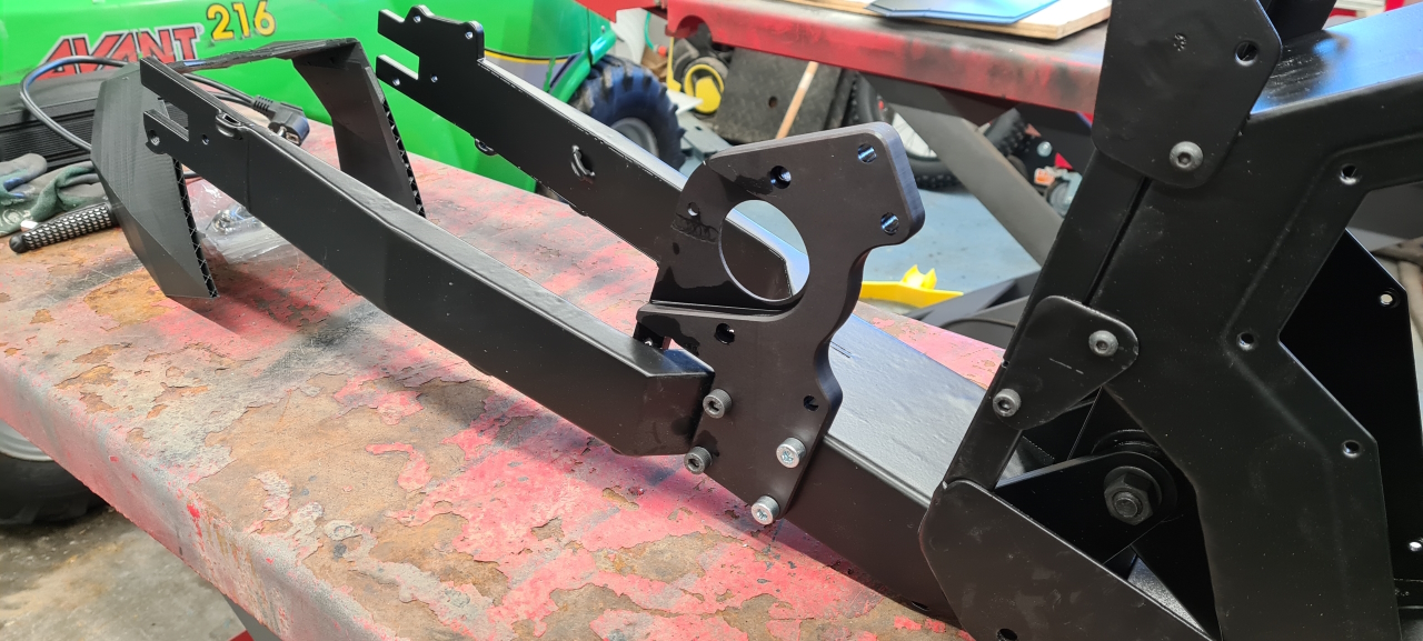
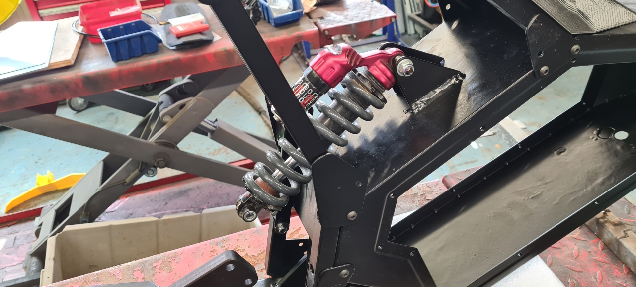
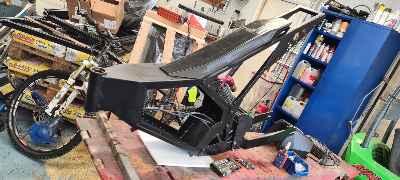
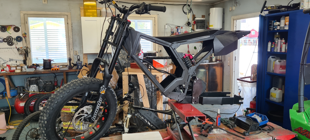
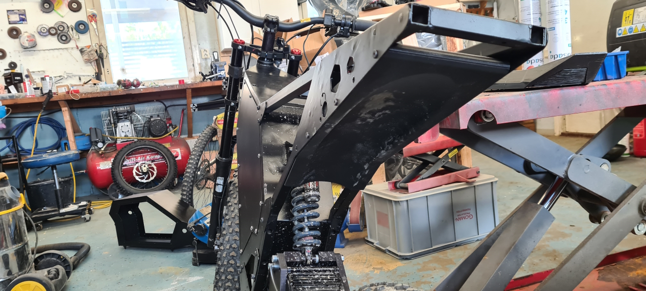
It’s quite a time consuming process but the result makes it totally worth it! When I had the anodization going in the garage I anodized all the parts for the second bike as well. I’ll post more about that frame later.Now that all the parts and the frame had the right color it was time for the final assembly. First the shock was installed to link the motor mount and rear swing to the frame.After that I installed the updated motor and temporarily put the seat on…
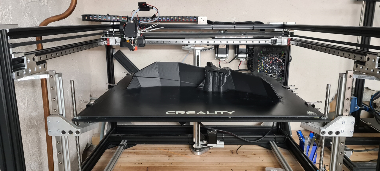
This was to be able to test the fit of the 3d printed rear fender, which was too small and required a couple more prototypes before I had a good fit.
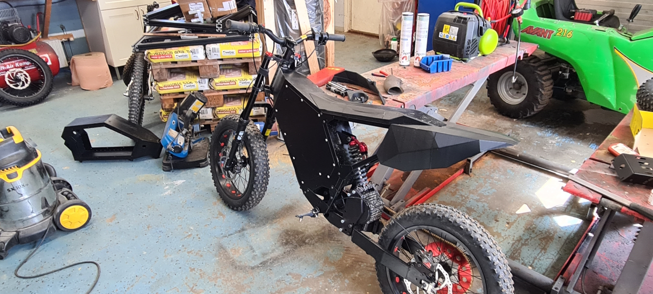
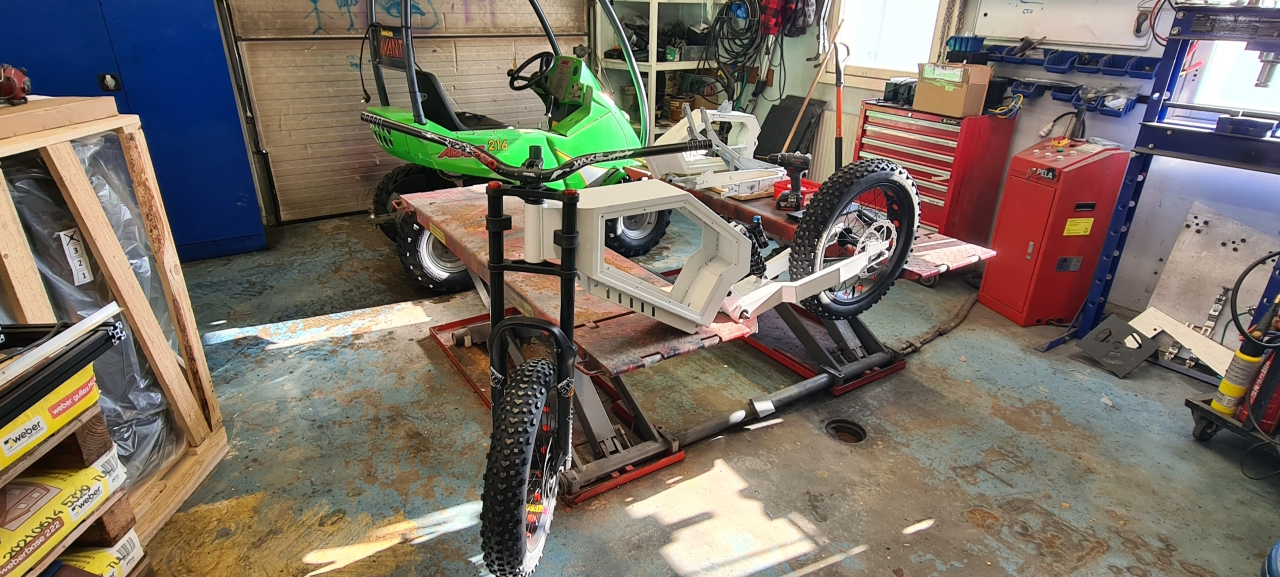
Once it’s there it looks pretty good.. (but later, after adding the aft part it looks a bit wierd, so a redesign of the rear fender is on the todo-list)Front fork, wheel and handlebars installed..
Rear wheel, chain and so on..
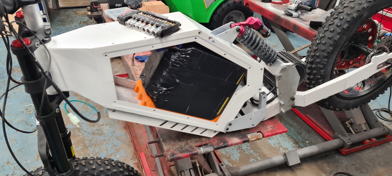
Now we’re getting an idea of what the finished bike will look like..Time to install the electronics. This one will run the ASI BAC2000 with the High Voltage map for the BigBlock motor. The battery and all the charging- and powerleads are installed. To hide all the cables and connectors the cover that’s supposed to house the controller in installed. The BAC2000 is way to big to fit in the controller housing so it’ll reside inside the battery compartment.
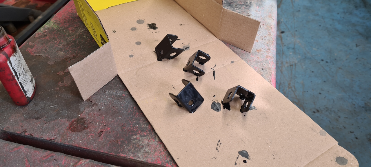
A while back I got lazy and decided not to make my own footpegs, so I ordered footpegs from Amazon for cheap. To mount these I made steel brackets on the manual mill and painted them black.The side covers are mounted. I’ll remove these later and make a proper seal between the cover and the frame to make it waterproof. When doing that I’ll also install a drain tube at the bottom of the battery compartment to get rid of all the moisture and water that might make its way into the box. No matter the steps you take to make the battery compartment waterproof water _will_ get inside and it’s important to let it escape somewhere..I’ve made a few attempts to make a front fender but for now I’ve decided that this part isn’t necessary. 🙂
Instead, for the time being, I wrapped the cable cover box in protective vinyl wrap. This’ll make it less sensitive to flying pebbles and sand.
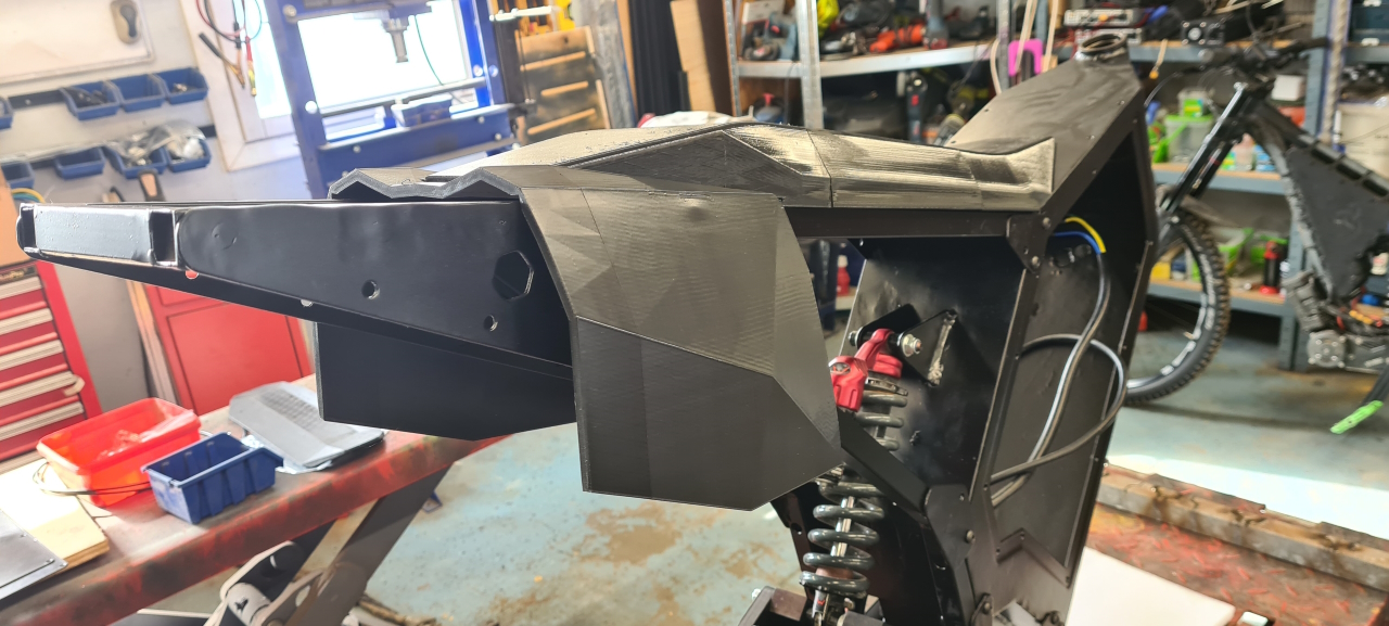
One of many concept prototypes for the front fender. The CAD model of this bike has been improved all through the project and now it’s a real good reference to get measurements and model parts into.The rear of the bike gets an inner fender to prevent all the water and dirt from sticking to the riders behind. I’ll make a fender that’ll sit closer to the wheel, protecting the motor from the muck getting tossed around by the rear wheel later. For right now the new seal on the motor will have to suffice to get some test riding done. Finally with the rear fender added the bike is pretty complete. There are parts to add and I’ll have to get rid of the Amazon footpegs and make my own since these were ridiculously flimsy – but they’ll work for now. I’ll also have to add a chain tensioner and I might have to make a smaller front sprocket to make the bike slower.. 🙂
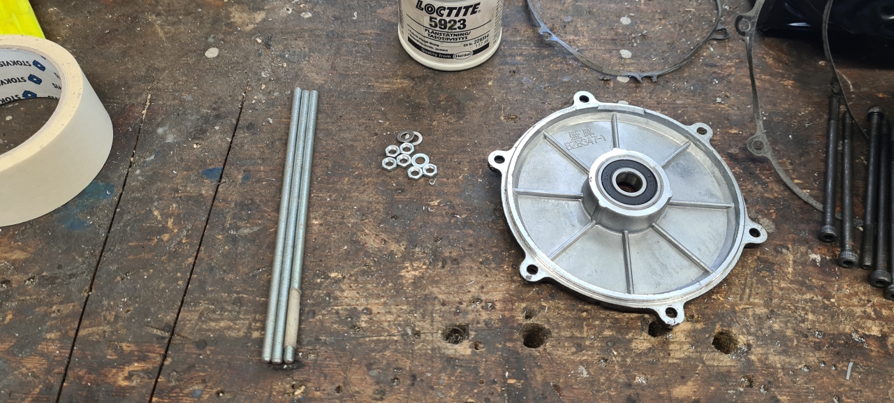
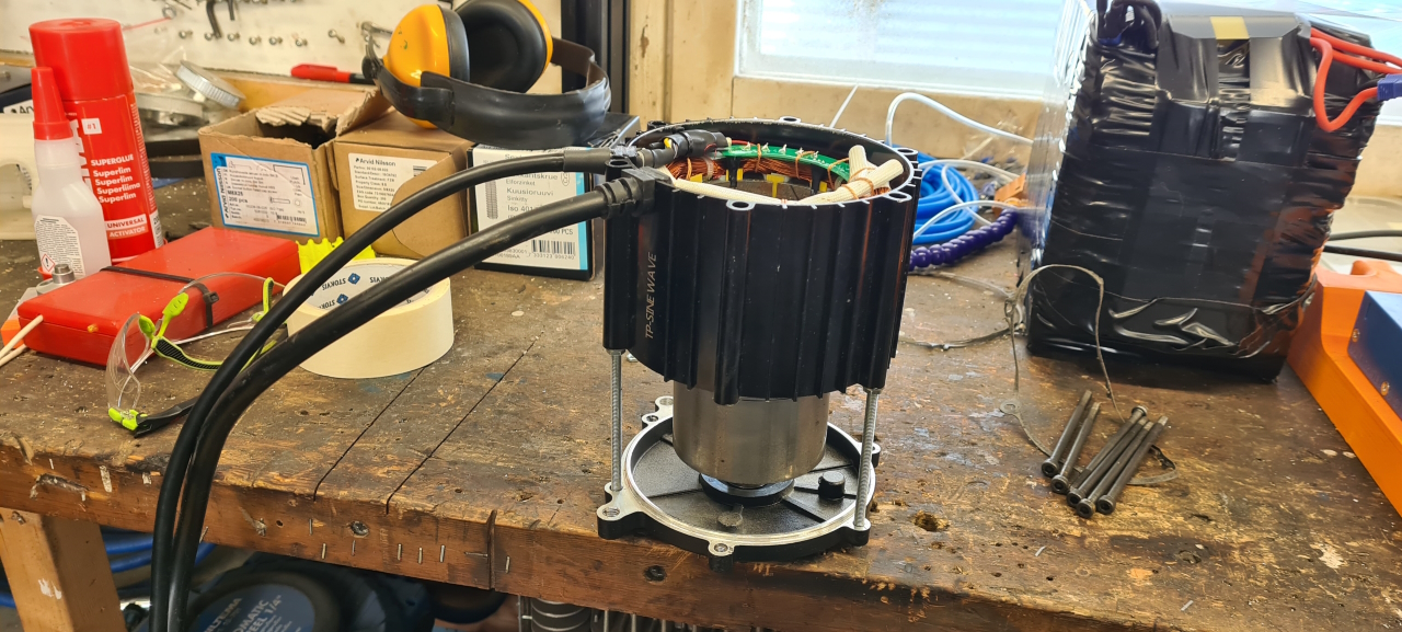
So, since the magnets in the rotor was super strong I’ve been a bit nervous about re-assembling the motor, but I got an idea..
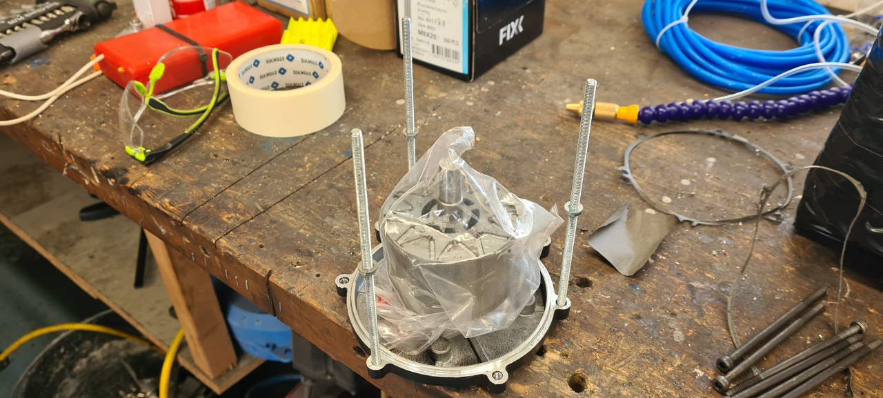
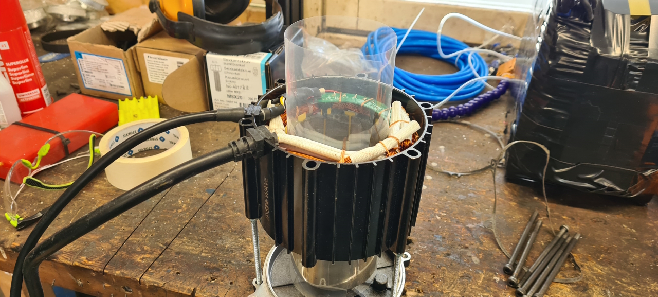
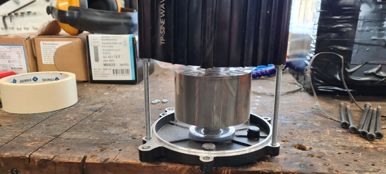
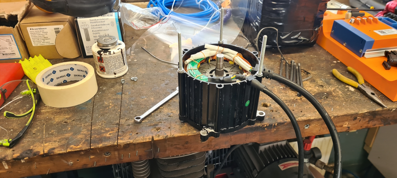
With three M5 all-thread rods and a few nuts..Threaded the rods into the top part of the motor and added nuts at a similar height on all rods..These would then support the stator allowing me to gently let it all the way down over the rotor without slamming together.To further protect the rotor I inserted a sheet of OH plastic in the air gap between rotor and stator. This is totally unnecessary but still..
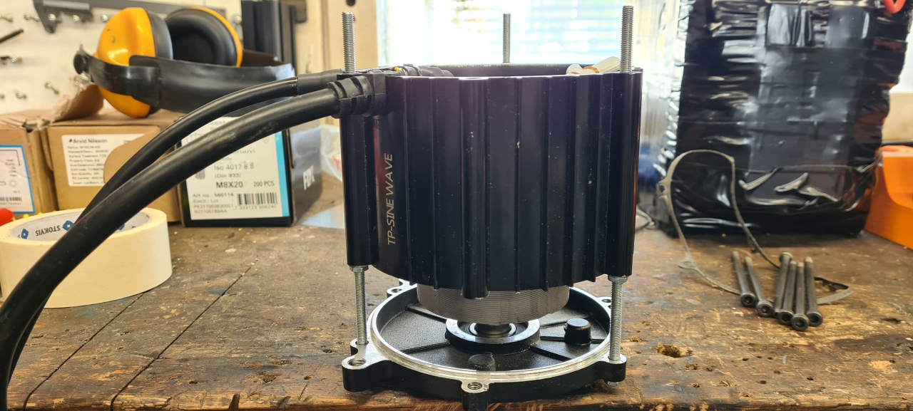
So, now it was just a matter of easing the stator down all the way. Most of the way I could just turn the nuts by hand but it’s the last centimeters that are hardest to control but the three-nut-solution made it super easy.
I let the motor sit for the liquid seal to cure for a day or two before adding some conformal coating to the hall sensor circuit board and to the thermistor wires to keep them out of the way of the rotor. Then I added the bottom cover and it was all done. Now I just need to do the same to my second motor.
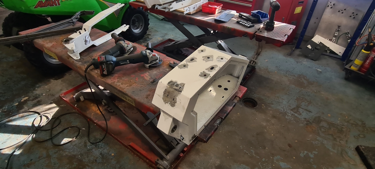
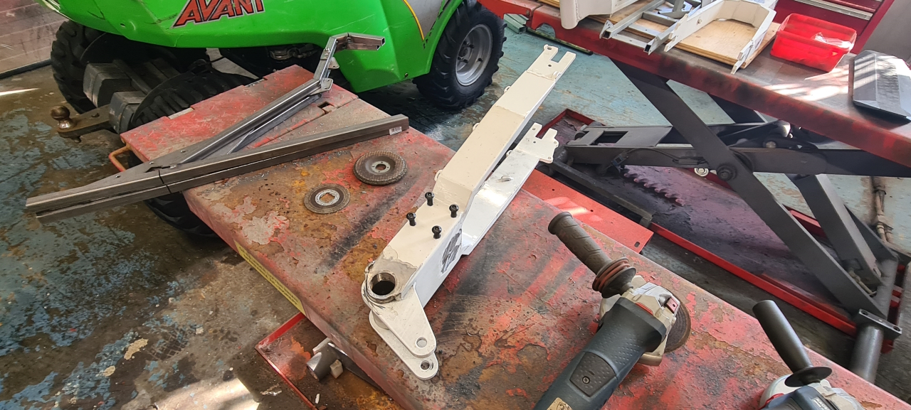
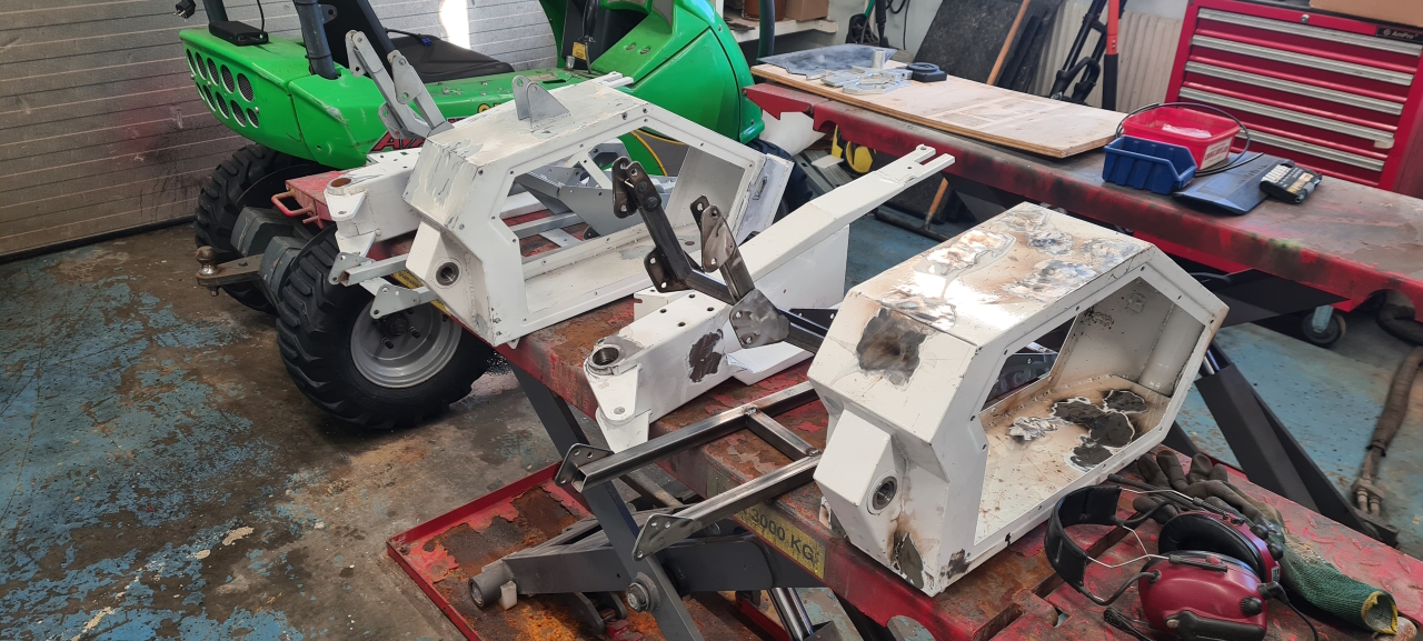
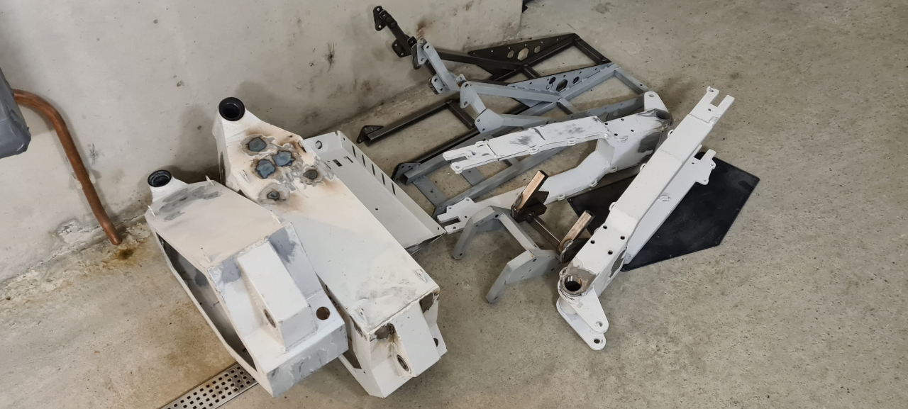
Frame preparation
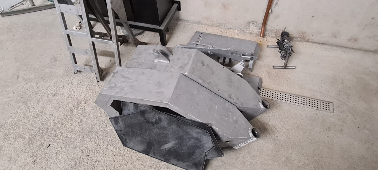
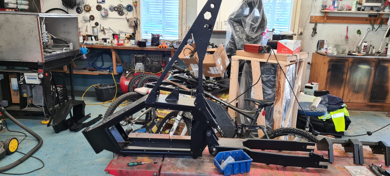
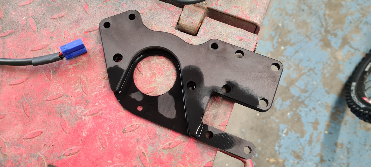
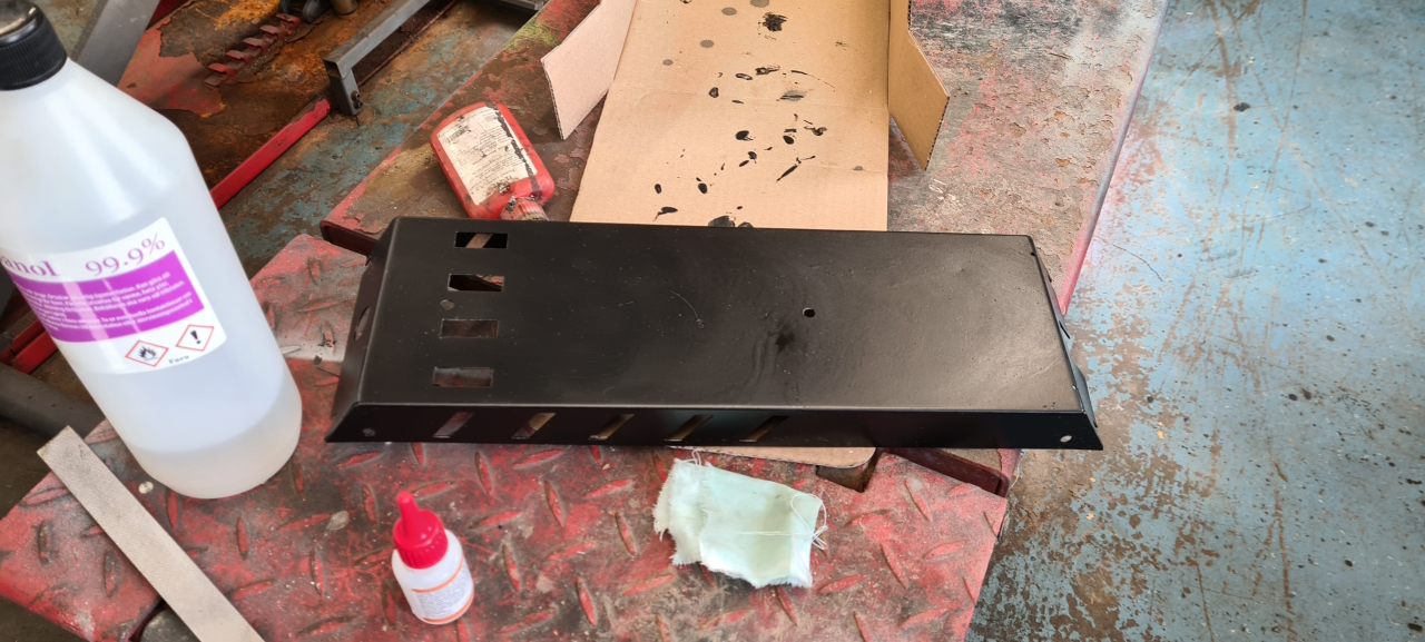
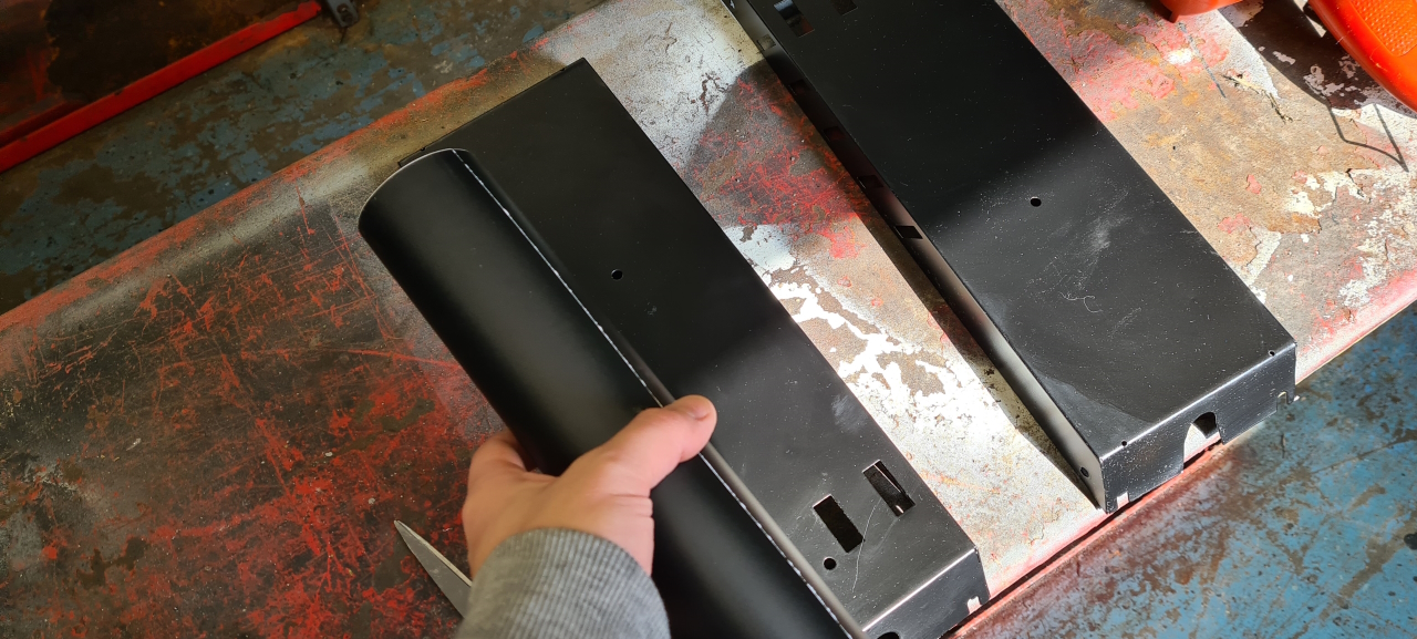
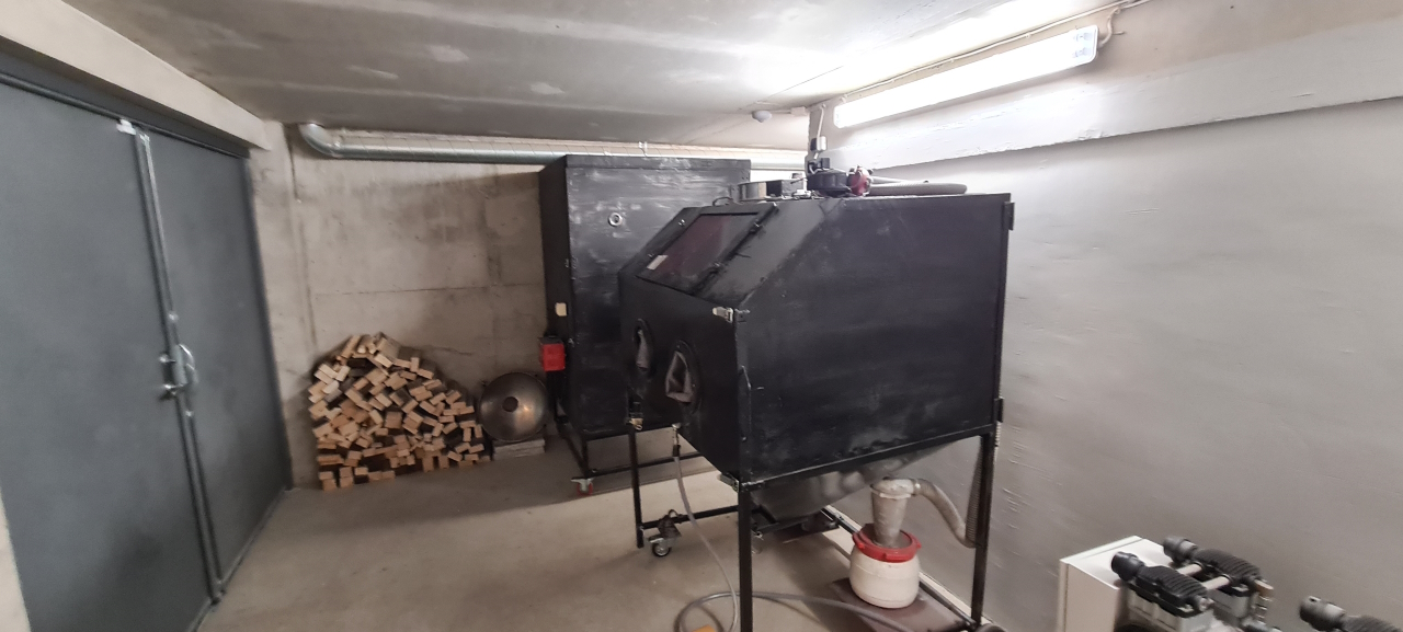
Before rebuilding the bike I wanted to get it painted and since a friend of mine has a complete powder coating setup we’re going to powder coat the entire thing. To do that I need to do some preparation to the frame and since it’s a bit cumbersome I decided to powder coat both my frames at the same time. The paint that’s on these frames are sketchy at best..I’m going to make a video of the entire build of this second bike. The first step in preparing the frame is plugging all the holes in the battery box. I simply welded all the smaller holes and made inserts for the larger ones.I drilled and tapped the mounting holes for the motor mount.After doing a bit of cutting and welding the atmosphere in my workshop is toxic, to say the least. I need to build a filtering solution to be able to breathe while working.After welding the subframe the second frame is ready for sand blasting and paint. I decided not to weld the mount for the rear shock onto the frame. Instead I’m going to make a bolt-on solution where I make a mount that bolts onto the frame at the right height. This will make the build and installation easier and I can drill the holes later when assembling the bike. So, now all the parts are ready for sand blasting..I’ve never used a proper sand blaster before but it turns out some of the paint that’s on the frame is real tough to get rid of. I spent a good 4 hours last night trying to strip the paint from all the parts and didn’t even finish two parts. Today I’m going to rough the paint up with a grinding wheel before sand blasting, hopefully this’ll let the blaster work better on the parts.
So, after testing the bike for a few trial runs it stopped working. Connecting to the controller I got an error saying ”Post static gate test” which usually means there’s a problem with the controller having a mosfet fused to ground or the postitive terminal.
So, a bit displeased I started taking the bike apart but before putting in an RMA I decided to test another controller I’ve got sitting around, and got the same error with that one.. so, the problem seemed to be with the motor, which was a bit wierd. Connecting my second motor to the controller confirmed that the motor was the issue since it ran without any problems.
After doing some measuring I was a bit confounded as all the resistances seemed to check out and sure enough when I connected the motor windings to the controller it all worked. However, when I connected the hall sensor array it stopped working again.. Hmm..
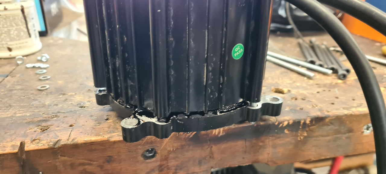
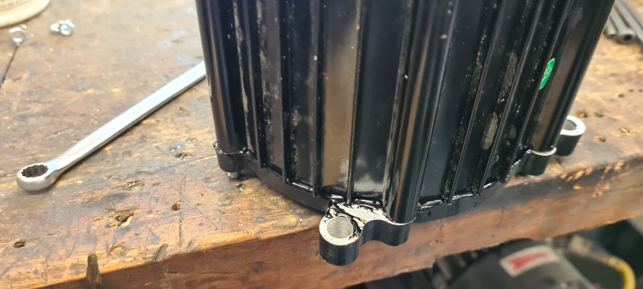
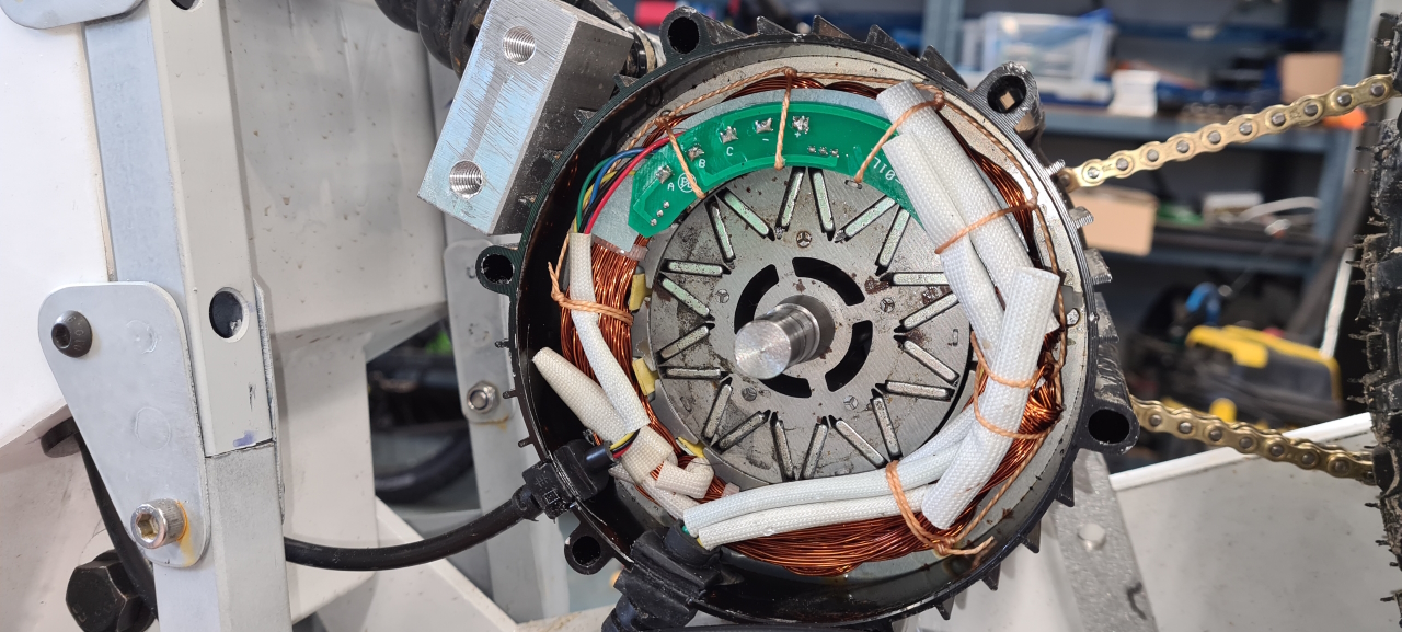
I just had to take the motor apart to find out what’s wrong with it, and on opening it up I found a bit of water inside that’s not supposed to be there. After drying the motor the error on the controller disappeared again and everything seems fine.. although, where the motor sits on the bike, just in front of the rear wheel, I’ll need to make sure water cannot get into the motor. Even though I’m adding all kinds of fenders the motor is going to be suscepted to moisture and water..
Taking the motor apart the seal that sits between the stator casing and the end bells on the motor crumbled to dust which is probably why the water got in there in the first place.
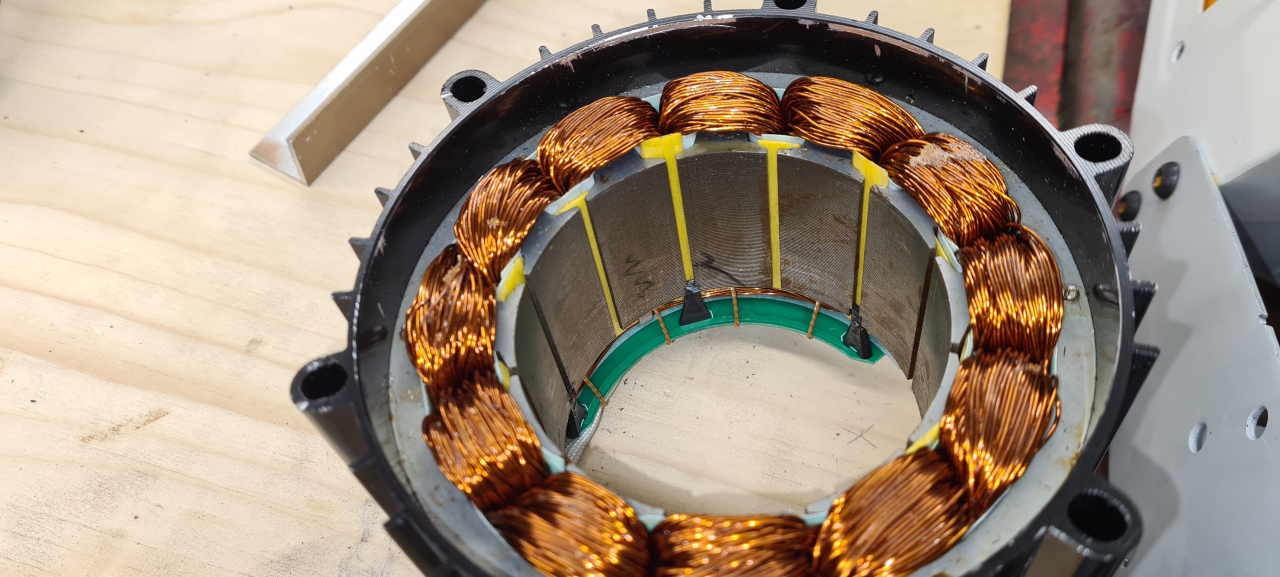
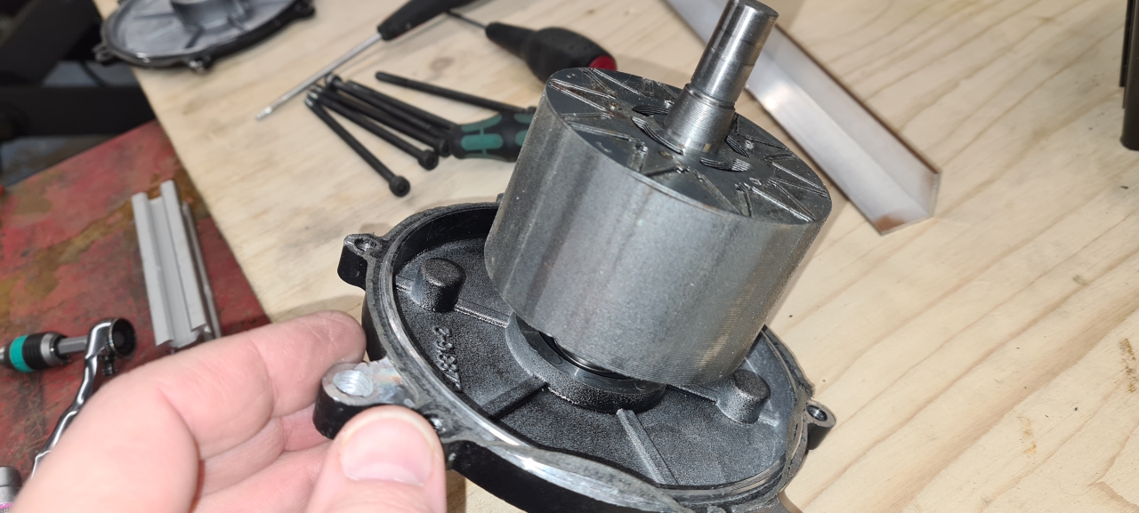
I decided to take the motor apart properly to check for damages and it turns out there was none. Getting the rotor out of the stator was insanely hard though as the magnets in the rotor is immensely powerful on this motor!
If you get your fingers caught between the stator casing and the end bell on the motor I guess you’d have to leave your fingertips inside the motor. I’m not looking forward to putting it back together again.. I’ll have to come up with some contraption to make it not slam back cause I reckon that’d make the motor self destruct and take half of the garage, both my hands and my left liver with it as it goes…
As I had the motor apart I thought I’d add a thermistor to be able to have the controller reduce power if the motor gets too warm. The Lightningrods motors come with a thermistor if you ask Mike to install one, which I happeded to forget..
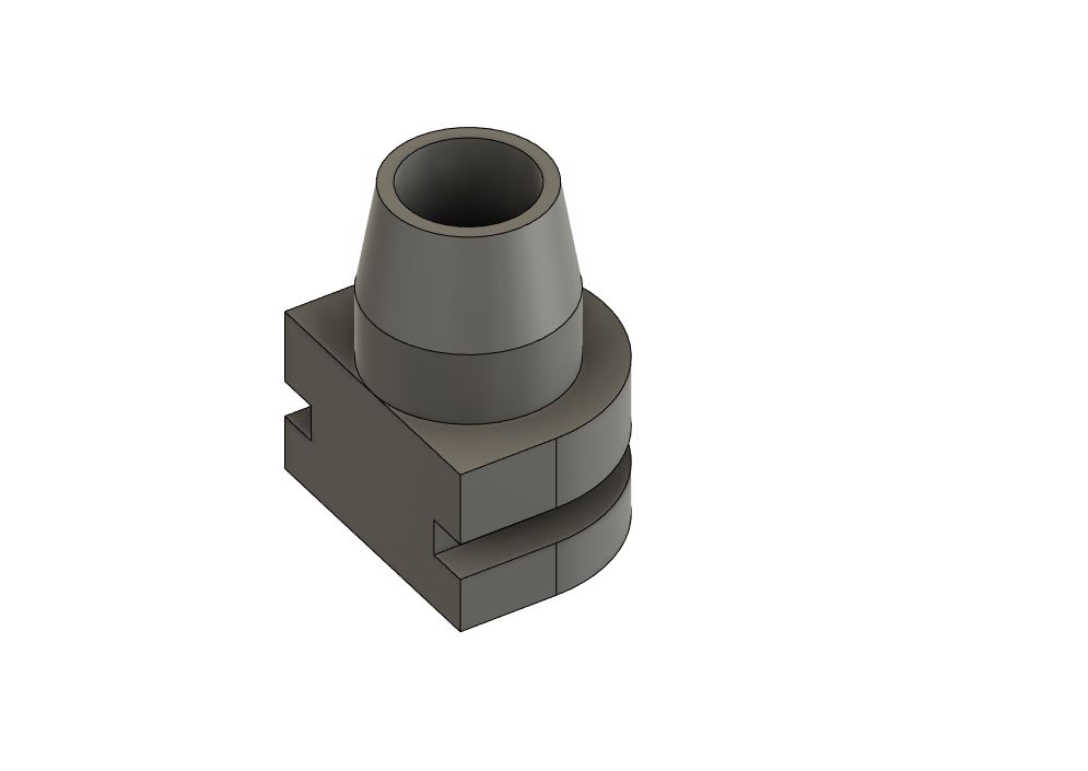
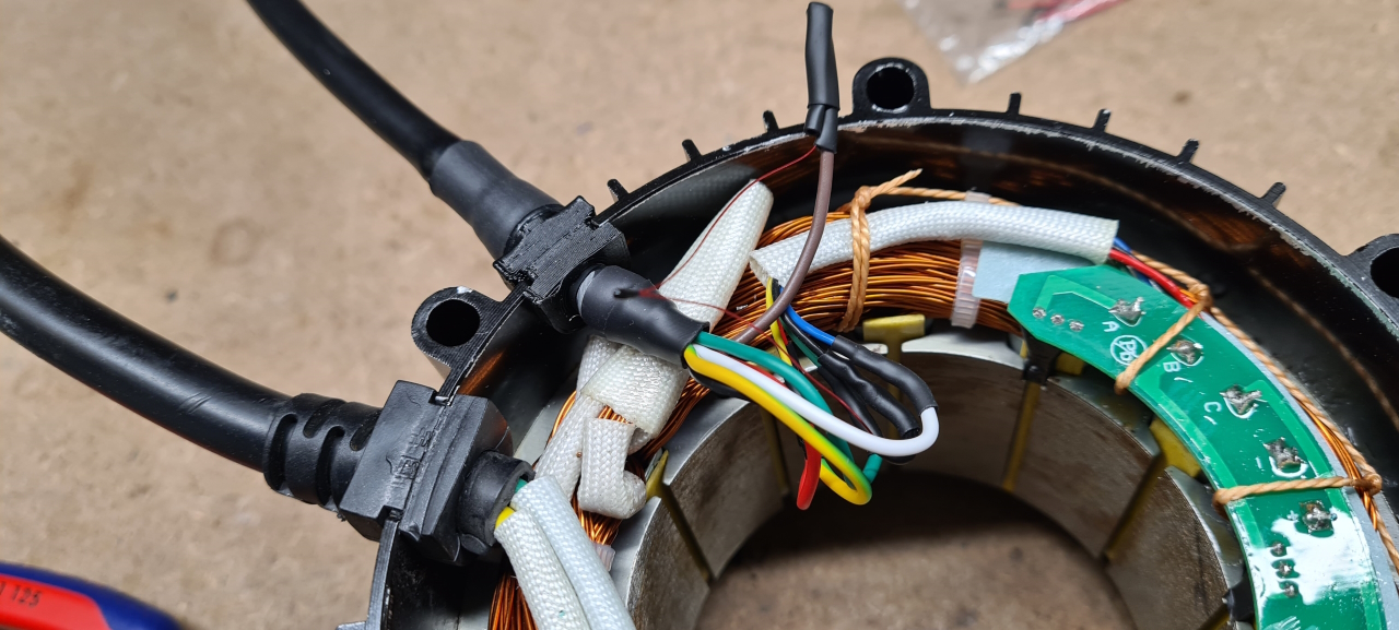
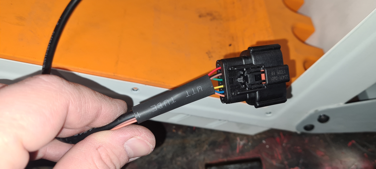
The normal way of adding a thermistor is to make a hole in the case and route a cable from the thermistor to the controller through there but I didn’t like the idea of adding another cable to the motor. Two is enough I think. So I instead opted to replace the 5 lead cable that goes to the motor originally with a 6 lead cable instead. To be able to fit the larger cable I had to make a new grommet for the motor casing though.
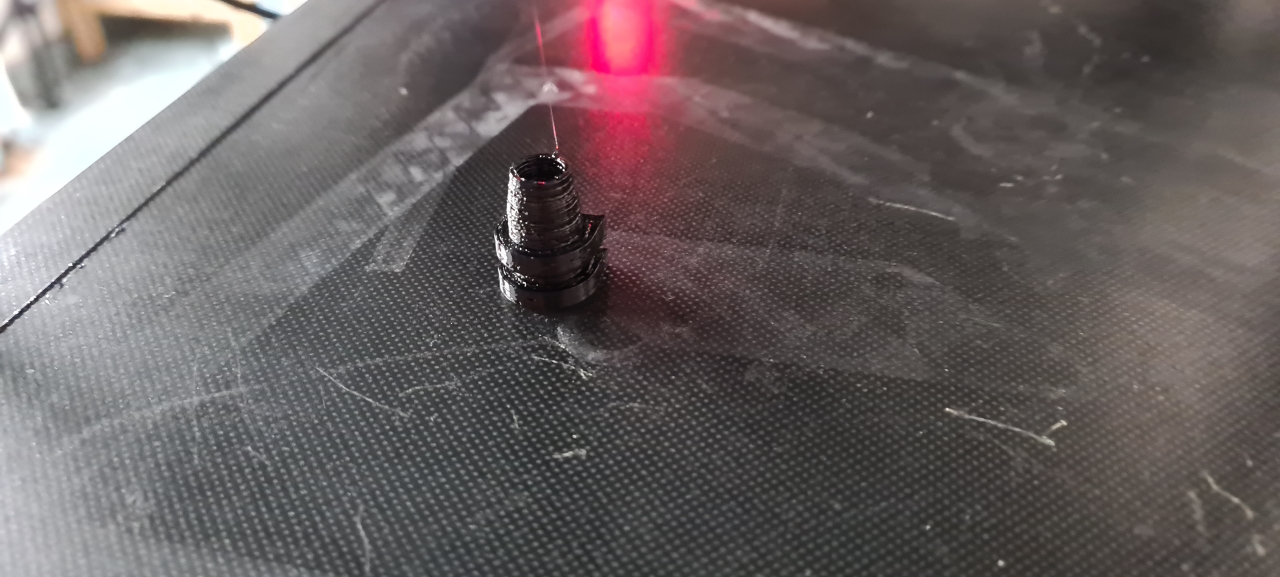
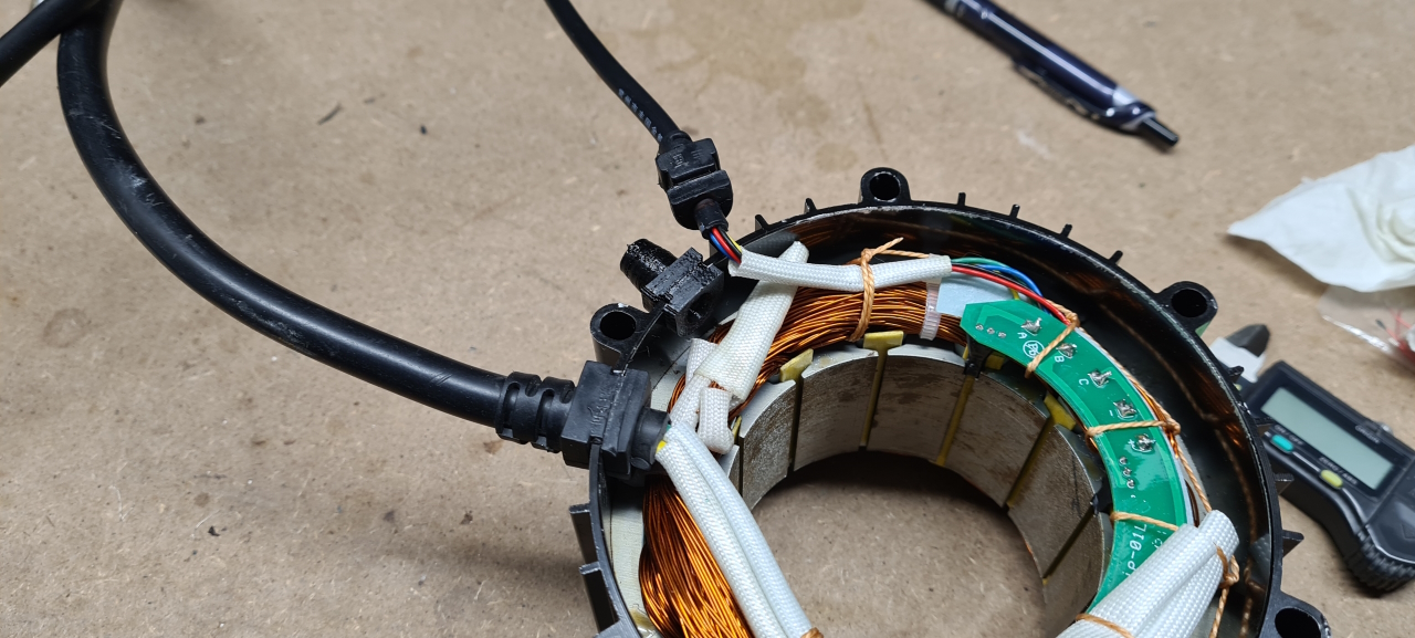
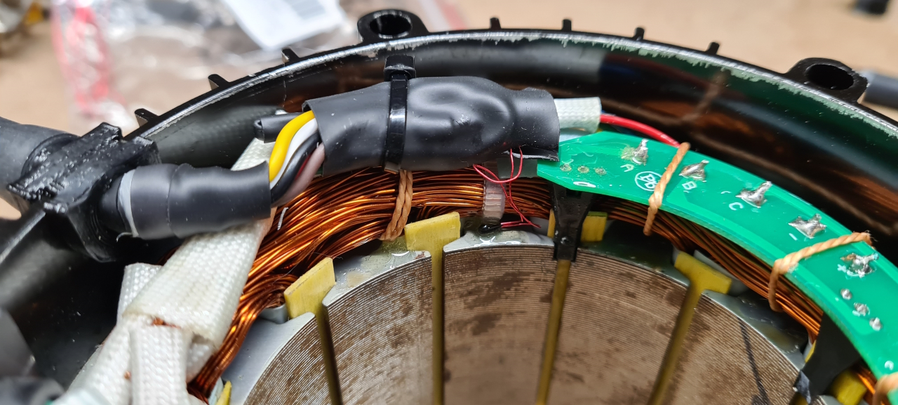
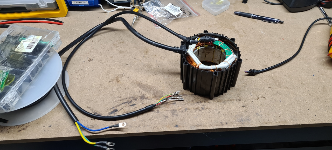
Fist a bit of CAD, and then I printed it from solid TPU.Turned out OK and pushing the cable into the grommet was SUPER hard, so it’s a tight fit.The grommet is a great fit in the motor too so it should make a good seal. I cut the original cable and soldered and insulated the new cable to the old, matching the colors as good as I could.I also soldered the thermistor between the negative lead and the new brown lead (colors for future reference by me) and went on with tidying everything up.I used epoxy to secure the thermistor to the motor as close to the rotor as I could and tucked all the wires away neatly. Taking some measurements everything seems to be in working order so the last step was to add molex crimp terminals to the other side of the added cable to fit the 6 pole connector for the controller.All done for now. Tomorrow I’ll try to get the rotor back inside the motor. I’ll add liquid seal to the end bells before putting it all together again hopefully keeping the water outside the motor for the future.
Taking the motor apart I saw that the conformal coating on the hall sensor PCB was missing in part, probably allowing the problem to occur in the first place. I used epoxy to cover the PCB to hopefully make the motor more resilient to failure in the future even though some moisture might get inside.
So, after having used the current 20s5p molicel pack for a couple of years it decided to give up during a ride in the snow a few weeks ago. It suddenly lost voltage and would not recharge and when I took it apart two cell groups were sitting at 0V. As I had taken a shortcut bypassing the 60A chinesium BMS to get the power output I wanted from the battery I guess this was bound to happen. The BMS at least prevented me from charging the battery when any cell group were at a bad voltage, so that’s good.
I took the pack apart and put all the 18650s through a thorough testing program and capacity measurement. All cells in the 18 cell groups that were at an OK voltage were good but the cells in the bad groups were at very low capacities if they took charge at all.
Before this ride I’ve had the bike sitting untouched for several months so I guess it’s gotten slowly discharged during this time and when I took it out for a ride pulling 100-ish amps from cells already low at charge it eventually killed them. (This is just me guessing at what happened).
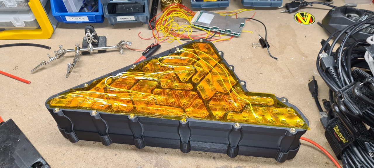
As the battery box I was using was a bit cumbersome to build and mount due to me trying to make a quick-change battery at the time I decided to design a new pack from scratch.
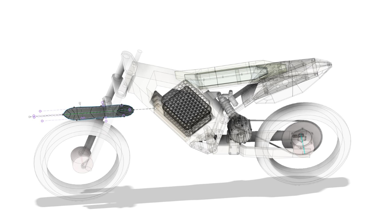
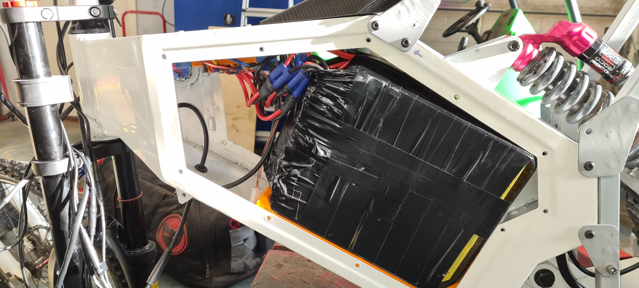
Fitting 100 cells in the swoop frame is tight fit, so I had to make some prototypes before finding the best shape to get an as-decent-as-possible battery layout that’d actually fit (and be able to mount) in the frame. To make it as sturdy as possible I could not fit the side covers before putting the pack in the frame so it’s tight.. 🙂
Since I’ve upgraded to the BAC2000, pulling A LOT more current from the battery (this might also be part of the reason for the failure of the old pack) I built the new pack as a copper/nickel sandwich that should be capable of providing all the amps I need. To save some money I only replaced the bad cells with cells I already had at home. Doing this it’s important to make sure the ”old” cells aren’t mixed with new cells as the drain profiles might differ causing individual 18650s to see more load than the average cell which could lead to failure. To give the pack the best chance to survive I installed an ANT BMS capable of 120A cont and 300A peak. This allowed me to route the power through the BMS even for the consumer and letting the BMS kill the power to the bike if any cell group goes low. The BMS can be monitored via bluetooth so I can keep track of the health of the battery too which is a nice feature to have.The pack looks nice and being a fair bit wider than the old pack doesn’t matter. As it sits it’s not in the way of anything when riding. The pack gives a good punch when slamming the throttle and the bike wants to lift the front wheel all the time which is awesome.
Hopefully this pack’ll last a couple of more years before needing a rebuild again.
So, it’s been a while since I last posted and it’s been a lot going on. I have had to rebuild the battery for my Radon Swoop which has taken quite some time with measuring all cells and cleaning everything up for re-use but there’s been a bit of progress on the RunBike project too.
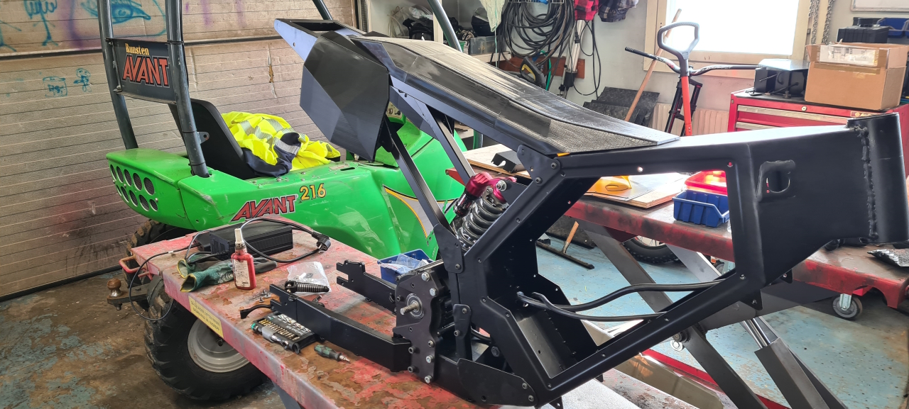
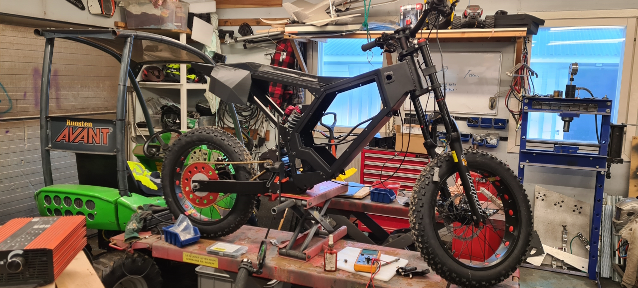
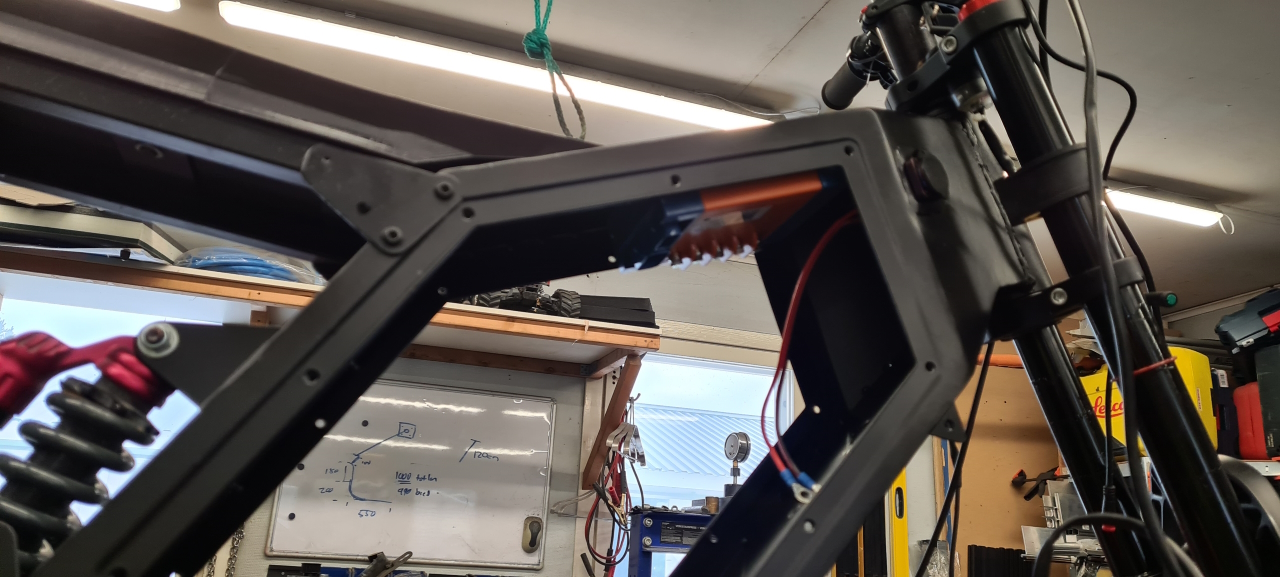
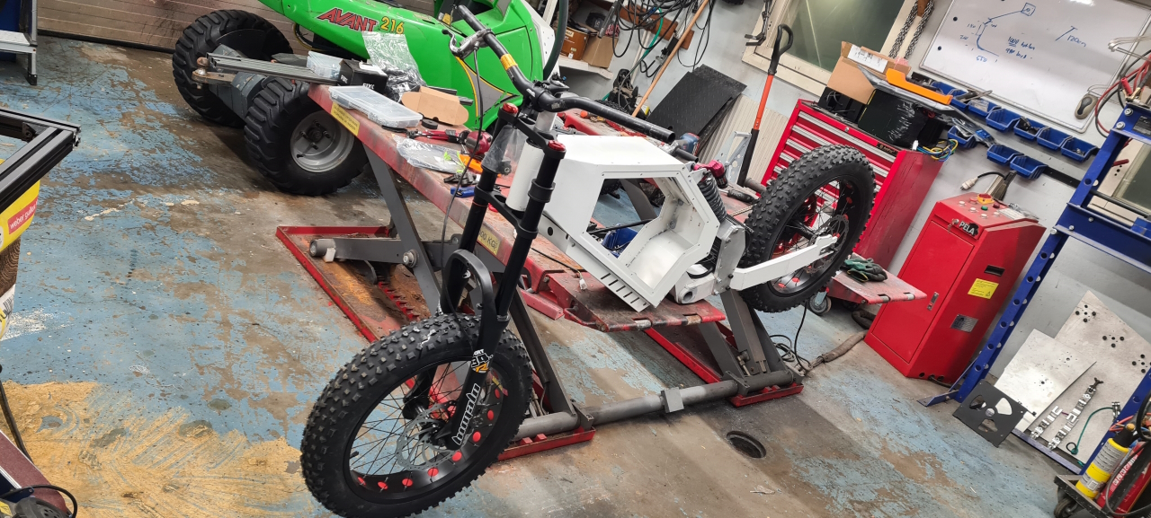
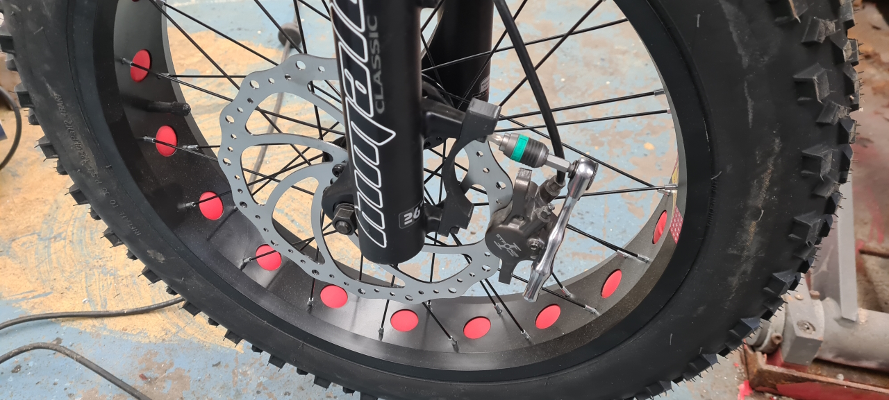
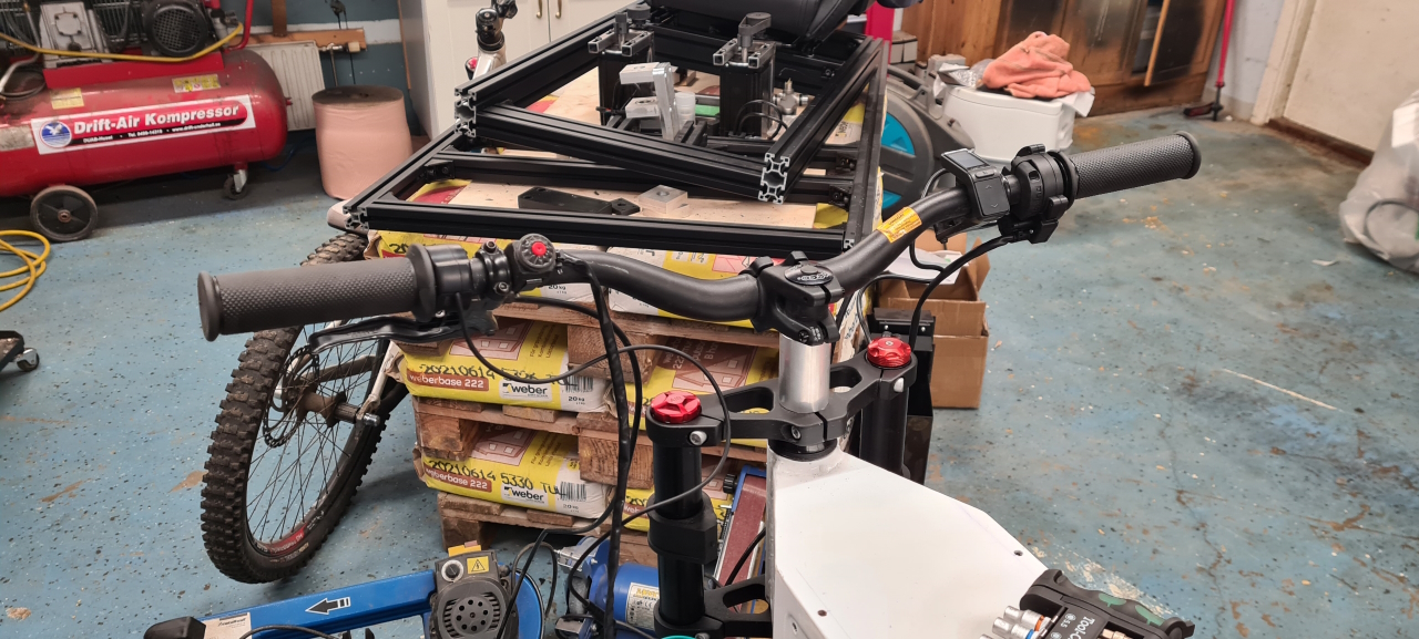
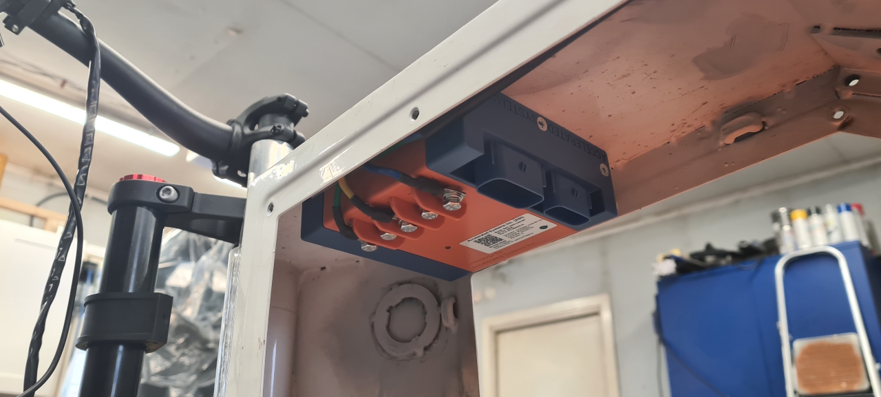
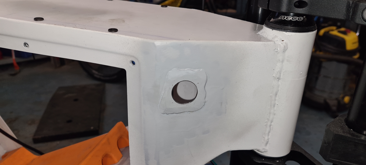
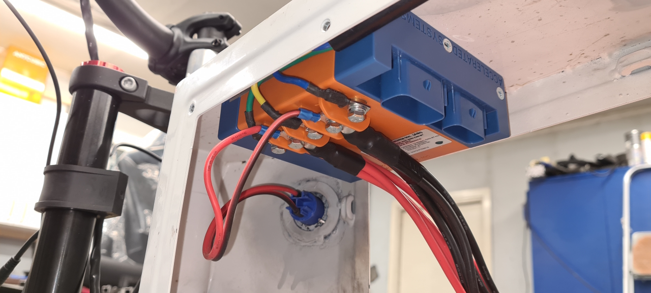
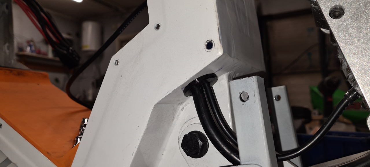
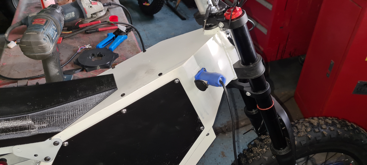
So, this kind of is where we left things off last time.To be able to fit the brakes on the 203mm discs I had to make some adapters. The first version I 3D-printed, until I got it all right and then I made it from aluminium.I have come up with a way to mount the battery pack which is a bit cumbersome to get in and out of the frame – but once it’s in there it really doesn’t have to come out..The cockpit of the bike is super clean, with just the tiny eggrider cluttering things up. There’s the domino full twist throttle on the right clustered with the front brake and eggrider display. On the left there’s the rear brake, a thumb-throttle mounted the wrong way around for regen braking and an emergency cutout which kills the controller. On the upper triple clamp I also added an ignition key which acts as the master on/off switch for the entire toy.The controller fits super nice in the frame box. Mounted in the top of the box it’s protected from any water that makes its way inside. I’ve welded all the holes in the box but water always finds its way, so I’ll be adding a drainage to the box at the lowest part too.The BAC2000 and BAC4000 are super easy to wire, and both use the same harness so upgrading the bikes will be super easy in the future. 🙂
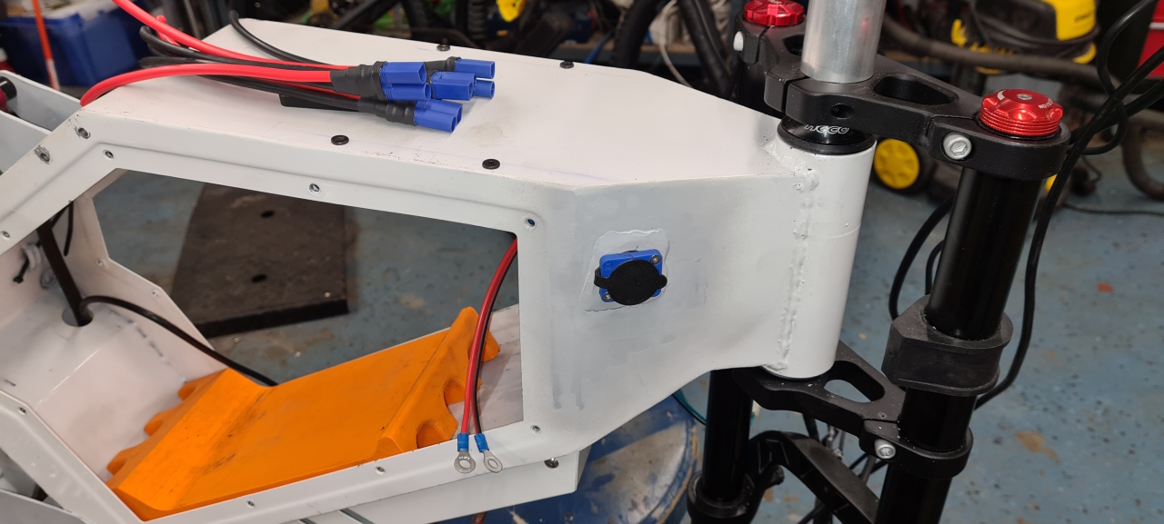
Drilled a 24mm hole, sealed and added the charge connector for the battery.
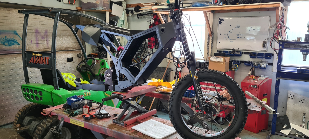
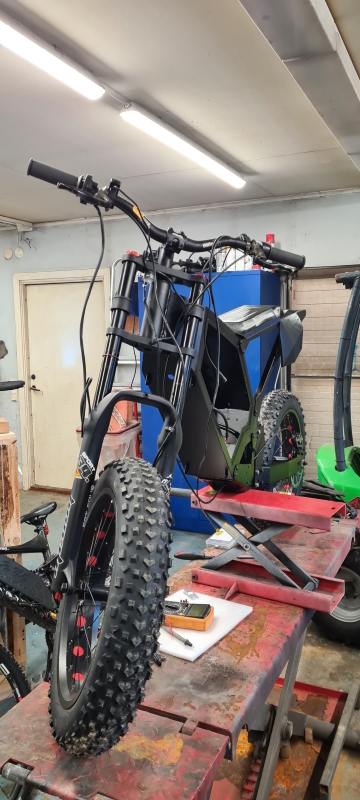
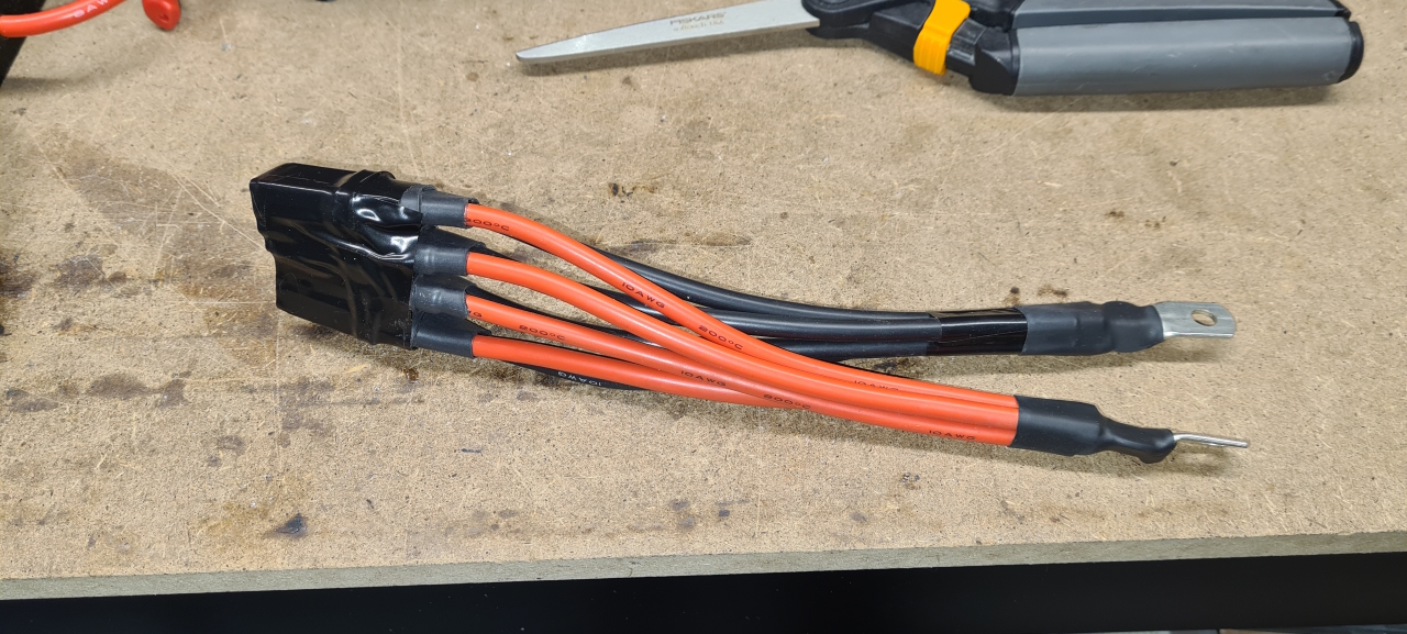
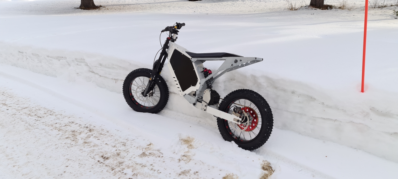
The battery has 4 pieces of EC5 connectors spreading the load equally over the pack cells, so the controller needs matching 4 connectors to draw current from.When all is connected this is what it looks like. Just the signal wires needed but those will be the last connectors I install as they’re in the way of the battery.I printed and added grommets to all cables going into the box. Partially for sealing the holes but also to protect the wires. All grommets are printed from TPU.The battery is finally installed and the battery box is ready to be closed. Everything will have to come out again for painting later on but first we have to test the bike out to see what modifications we have to make before paint.So, finally it’s time for the long awaited test ride..
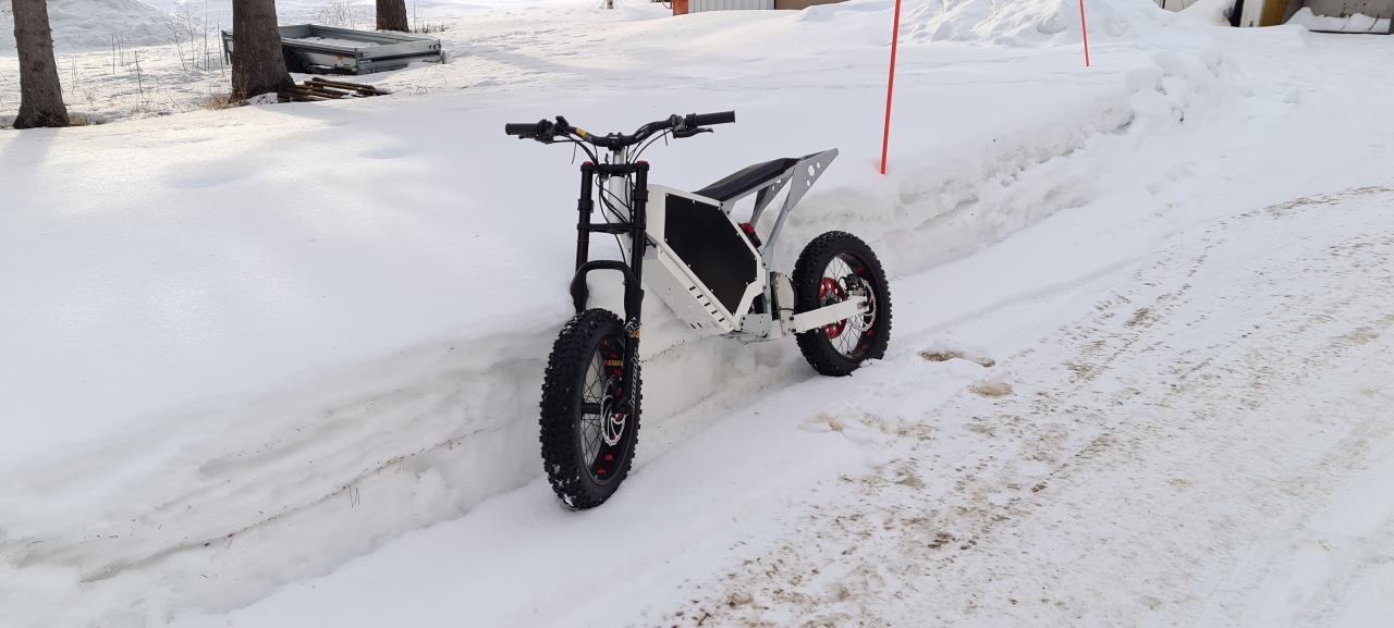
The bike runs super smooth with tons of acceleration and a seemingly high top speed. The spedometer isn’t calibrated yet so I have no idea how fast I’m going and the roads are covered with ice, but it feels nice! The torque makes the motor pull the rear wheel forwards though so I’ll need to add a chain tensioner to secure it in place. I also need to add brake fluid to the rear brake, which is good to have even though the regen braking is awesome! Also, footpegs will be nice to have to be able to ride standing up!
After a bit of riding I had to test the charge inlet out. Everything works as it should and I get a good bluetooth connection to the BMS inside the box.
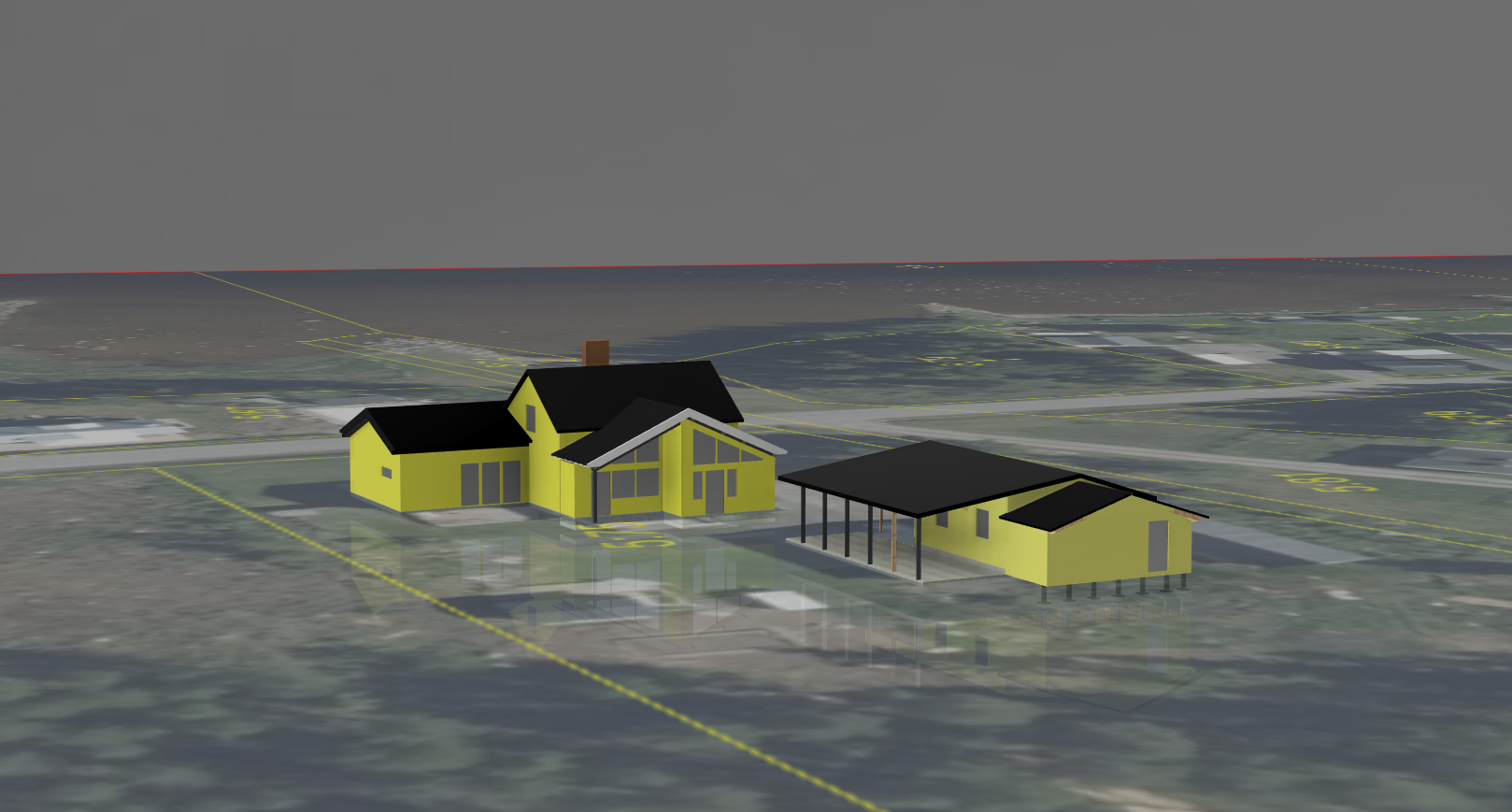
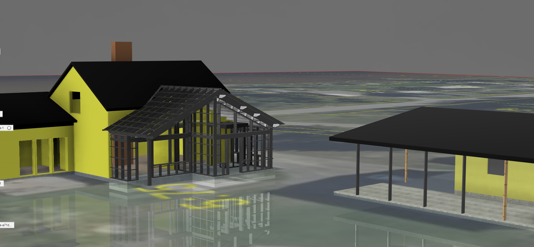
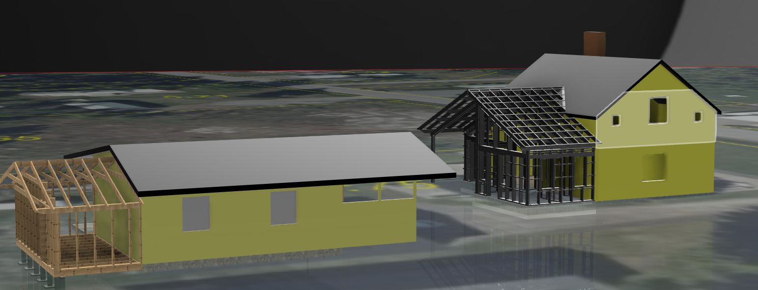
So, we’re planning on finishing the house project this summer. We’re going to extend the house a bit and add a lot of new windows and make the interior more open and spacious.This is a quick sketch on how we’re going to build the extension. Hopefully we’ll get an OK from the authorities to do this. The footprint of the house will be the same but the roof’ll be a bit higher and steeper.Since we’re always in need of more storage space we’re thinking of adding a shed on the back of the garage/workshop too. This’ll be insulated as the garage and we’ll use heat from the garage to keep this space at a few degrees C in the winter.
More updates will come as the project commences. This will be a huge project and the plan is to get the foundation and roof up this summer to be able to seal and insulate the house before winter.